
Automatic pneumatic dredging valve

A dredging valve, automatic technology, applied in the direction of conveyors, transportation and packaging, conveying bulk materials, etc., can solve the problems of abnormal air supply, aging of exposed pipelines, high price, etc., to prevent easy aging or damage, air leakage, Inexpensive and fast-response effects to make and use

Active Publication Date: 2016-05-25
ZOUPING CHUANGXING ENVIRONMENTAL PROTECTION EQUIP
View PDF6 Cites 6 Cited by
  • Summary
  • Abstract
  • Description
  • Claims
  • Application Information

AI Technical Summary

Problems solved by technology

[0002] The granular material conveying system widely used in the fields of thermal power, metallurgy, chemical industry, etc. has the problem that the material often blocks the pipe. At present, the method to solve the above problem is to install a high-pressure gas auxiliary connected to the compressed air pipe on the material conveying pipe. Blowing valve, when the pipe is blocked, the device instantly fills a large amount of high-pressure gas into the conveying pipe to blow away the blocked material and make the pipe unblocked. The existing blowing auxiliary valve needs an independent detection device to realize timely detection Material blockage increases the pressure and controls high-pressure gas blowing into and removing blockages. However, the existing detection devices have the following disadvantages: 1. They are all composed of complex and expensive electrical components, and their cost is high. , the electrical components are not suitable for the harsh working environment of the granular material conveying system, and the failure rate is extremely high; 2. The ventilation pipeline is exposed outside the valve body, and the exposed pipeline is often aged or damaged during use and cannot supply gas normally. Therefore, the existing high-pressure gas-assisted blowing valve cannot meet the actual use needs of users

Method used


Image

  • Automatic pneumatic dredging valve

Examples


Embodiment Construction

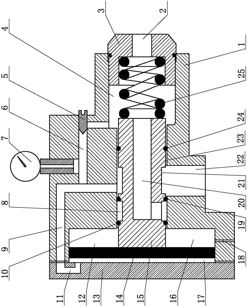
[0009] Such as figure 1 As shown, the pneumatic automatic dredging valve of the present invention includes a valve body 1, a spring chamber 4, a ejector rod chamber 23 and a valve chamber 12 are provided in the valve body 1, and the valve body 1 is provided with an end installation end of the valve chamber 12 Cover 13, valve body 1 is provided with spring chamber 4 at one end to install spring gland 3, ejector rod chamber 23 communicates with valve chamber 12 and spring chamber 4 respectively, valve disk 14 is installed in valve chamber 12, valve disk 14 will valve The film cavity 12 is divided into two independent first chambers 16 and second chambers 17. The ejector rod 15 is installed in the ejector rod chamber 23. There is a certain gap between the ejector rod 15 and the ejector rod chamber 23 so that the ejector rod 15 can move axially. And keep the second chamber 17 connected with the conveying system pipeline, spring 25 is installed in the spring cavity 4, the two ends ...


PUM


Abstract

An automatic pneumatic dredging valve comprises a valve body. A spring cavity, a mandrel cavity and a valve plate cavity are formed in the valve body. An end cover is installed at the end, provided with the valve plate cavity, of the valve body, a spring gland is installed at the end, provided with the spring cavity, of the valve body, the mandrel cavity is communicated with the valve plate cavity and the spring cavity, a valve plate is installed in the valve plate cavity and separates the valve plate cavity into a first chamber and a second chamber which are independent and are not communicated, a mandrel is installed in the mandrel cavity, a certain gap is formed between the mandrel and the mandrel cavity, a spring is installed in the spring cavity, the two ends of the spring are in contact with the spring gland and the mandrel respectively, one end of the mandrel is in contact with the valve plate, and the spring can provide reset force for the valve plate through the mandrel. The automatic pneumatic dredging valve is low in manufacturing and using cost and accurate and stable in running, and has the advantages of being large in instant inflating amount, high in responding speed and blocking removing efficiency, stable in running, simple in structure and convenient to machine and assemble.

Description

technical field [0001] The invention relates to a pneumatic automatic dredging valve. Background technique [0002] The granular material conveying system widely used in the fields of thermal power, metallurgy, chemical industry, etc. has the problem that the material often blocks the pipe. At present, the method to solve the above problem is to install a high-pressure gas auxiliary connected to the compressed air pipe on the material conveying pipe. Blowing valve, when the pipe is blocked, the device instantly fills a large amount of high-pressure gas into the conveying pipe to blow away the blocked material and make the pipe unblocked. The existing blowing auxiliary valve needs an independent detection device to realize timely detection Material blockage increases the pressure and controls high-pressure gas blowing into and removing blockages. However, the existing detection devices have the following disadvantages: 1. They are all composed of complex and expensive electri...

Claims


Application Information

Patent Timeline
IPC IPC(8): B65G53/66
CPCB65G53/66B65G2201/042
Inventor 朱汉超韩香莲
Owner ZOUPING CHUANGXING ENVIRONMENTAL PROTECTION EQUIP
Learn More