Automatic positioning lock and anti-misoperation sliding casement door and window hardware system and method

A technology for preventing misoperation and pushing and pulling doors and windows, which is applied to the layout of windows/doors, building locks, and wing leaves, etc., and can solve problems such as inability to realize automatic positioning, locking and/or anti-misoperation

Active Publication Date: 2016-05-25
佛山凯森贝格建筑五金有限公司
View PDF5 Cites 5 Cited by
  • Summary
  • Abstract
  • Description
  • Claims
  • Application Information

AI Technical Summary

Problems solved by technology

[0008] The purpose of the present invention is to solve the problems in the prior art that automatic positioning, locking and / or anti-misoperation functions cannot be realized when sliding doors and windows and horizontal hinged doors and windows move to different positions on the door and window frames. To solve the problems existing in the prior art, provide an automatic positioning lock and an anti-misoperation push-pull side-hung door and window hardware system

Method used


Image

  • Automatic positioning lock and anti-misoperation sliding casement door and window hardware system and method
  • Automatic positioning lock and anti-misoperation sliding casement door and window hardware system and method
  • Automatic positioning lock and anti-misoperation sliding casement door and window hardware system and method

Examples


Embodiment 1

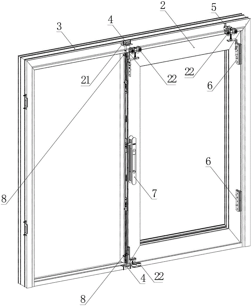
[0063] Embodiment 1, the anti-misoperation automatic locking device 4 also includes a first spring 12, the anti-misoperation contact block 8 is arranged on the housing 9 through the first spring 12, and the limit position of the anti-misoperation contact block 8 is the first The position where the spring 12 is naturally opened, and the non-limit position is the position after the first spring 12 is compressed (as an alternative embodiment of the embodiment, the anti-misoperation contact block 8 is arranged on the housing 9 through the first spring 12, and the anti-misoperation The limiting position of the misoperation contact block 8 is the position after the first spring 12 is compressed, and the non-limiting position is the position where the first spring 12 is naturally opened. Such a person skilled in the art knows that the replacement of the usual means can also be realize the technical scheme of the claims of the present invention).

[0064] Further, the anti-misoperatio...

Embodiment 2

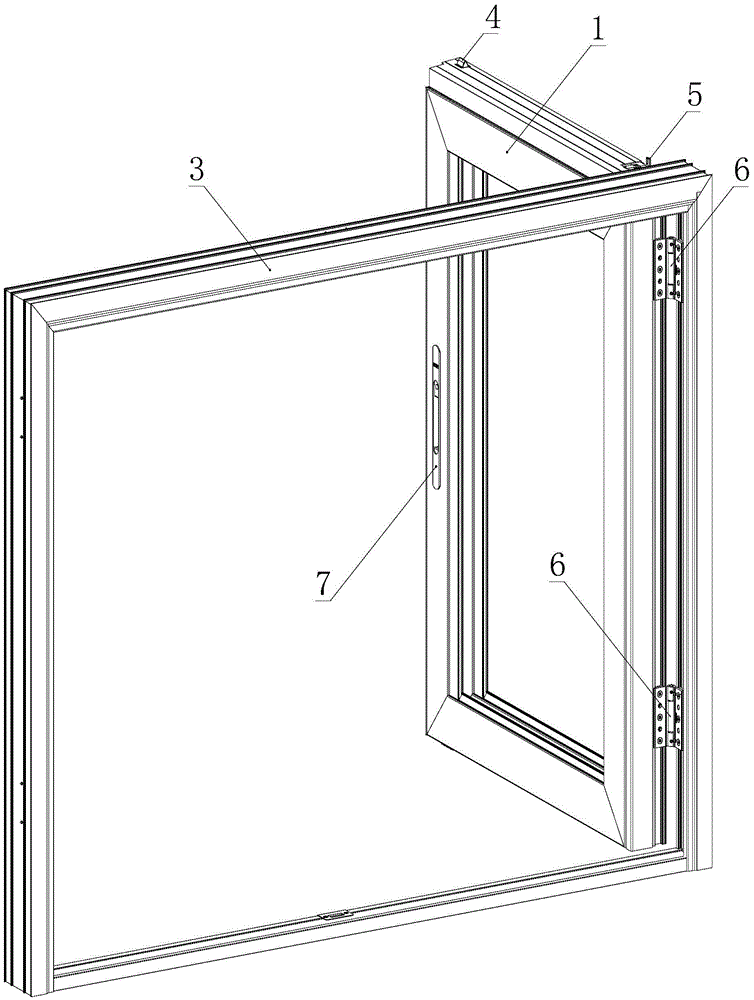
[0080] The anti-misoperation limiting device 5 also includes a third spring 31, and the anti-misoperation L-shaped column 26 is arranged on the anti-misoperation fixed seat 27 by the third spring 31, and the position limiting position of the anti-misoperation L-shaped column 26 is the first The natural loose position of three springs 31, the non-limiting position of anti-misoperation L-shaped post 26 is the compression position when the third spring 31 is compressed (as the implementation mode that embodiment replaces, anti-misoperation L-shaped post 26 can not adopt the first Three springs 31 are directly controlled by manual mode, or the anti-misoperation L-shaped column 26 slides on the anti-misoperation fixing seat 27 through the transmission lever to realize the switching between the limit position and the non-limit position); when adopting the third For the spring 31, in a preferred embodiment, the number of the third spring 31 is two, and the third spring 31 can be made ...


PUM


Abstract

The invention discloses an automatic positioning lock and anti-misoperation sliding casement door and window hardware system and method. The system comprises a casement door and window sash, a siding door and window sash, a door and window frame, an anti-misoperation automatic lock device and an anti-misoperation limiting device. The casement door and window sash is arranged in the door and window frame through hinges. The sliding door and window sash is arranged in the door and window frame in a sliding mode. The sliding door and window sash has an original locking position and an overlapping position, at the original locking position, the sliding door and window sash slides on the door and window frame, and at the overlapping position, the sliding door and window sash slides on the casement door and window sash. When the sliding door and window sash is at the overlapping position, the casement door and window sash can drive the sliding door and window sash to be opened outwards through the hinges. The casement door and window sash and the door and window frame are automatically locked and/or automatically unlocked through the anti-misoperation automatic lock device. When the casement door and window sash is at the overlapping position, the sliding door and window sash and the casement door and window sash can be automatically limited and/or automatically unlimited through the anti-misoperation limiting device.

Description

technical field [0001] The invention relates to the technical field of push-pull side-hung doors and windows, and specifically relates to a push-pull side-hinged door and window hardware system capable of automatically positioning locks and preventing misoperations when the door and window frame moves to different positions and its use method. Background technique [0002] From the perspective of opening methods, doors and windows mainly include two types: side opening and push-pull. One side of the side-opening door and window is pivotally connected or hinged to the door and window frame, and can be opened by rotating around its pivot or hinge; the push-pull type of door and window is limited in the sliding groove of the upper and lower parallel door and window frame or on the guide rail. It can move in the direction of the door and window frame. The advantage of the former is that the doors and windows can be fully opened and the lighting area is large. The disadvantage i...

Claims


Application Information

Patent Timeline
Patent Type & Authority Applications(China)
IPC IPC(8): E05B17/00E05B65/00E06B3/50
CPCE05B17/00E05B65/00E06B3/50E05B2017/0095E06B3/5081
Inventor 刘祥
Owner 佛山凯森贝格建筑五金有限公司
Why Eureka
Try Eureka