Zero-pivot and large-corner crossed reed type flexible hinge

A technology of flexible hinges and large rotation angles, which is applied in the directions of pivot connections, joints, manipulators, etc., can solve problems that affect motion accuracy and cannot be overcome, and achieve the effect of improving rotation accuracy, reducing errors, and fewer structural components

Active Publication Date: 2016-05-25
XIDIAN UNIV
View PDF9 Cites 18 Cited by
  • Summary
  • Abstract
  • Description
  • Claims
  • Application Information

AI Technical Summary

Problems solved by technology

The cross-reed flexible hinge can provide a relatively large range of rotation angles, but the ideal rotation center has the above-mentioned axial drift during the rotation process, and the axial drift increases rapidly with the increase of the rotation angle, seriously affecting the motion accuracy, which cannot be achieved in practical applications. overcome

Method used


Image

  • Zero-pivot and large-corner crossed reed type flexible hinge
  • Zero-pivot and large-corner crossed reed type flexible hinge
  • Zero-pivot and large-corner crossed reed type flexible hinge

Examples


Embodiment 1

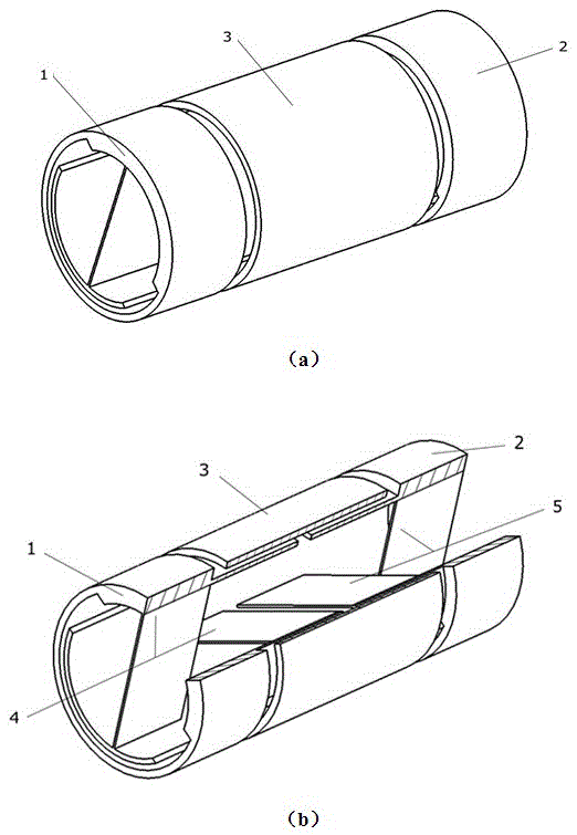
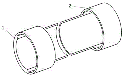
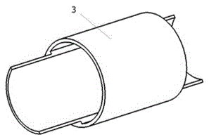
[0027] Such as figure 1 As shown, a zero-axis drift large-angle cross-reed type flexible hinge at least includes a left outer rotating part 1, a right outer rotating part 2, a rigid middle part 3, a left crossing reed 4 and a right crossing reed 5; The rotating part 1, the rigid middle part 3 and the right outer rotating part 2 are placed coaxially on the left, middle and right in sequence, and there is a certain gap between the left outer rotating part 1 and the right outer rotating part 2 and the rigid middle part 3 to ensure the rigid middle Part 3 does not contact and rub against the left outer rotating part 1 and right outer rotating part 2 during the movement process, and also allows the rigid middle part 3 to have a certain movement along the direction perpendicular to the rotation axis of the flexible hinge; the left cross reed 4 Place the right cross reed 5 in a collinear manner with the cross line, the reed arrangement of the right cross reed 5 and the left cross ree...

Embodiment 2

[0035] Such as Figure 6 As shown, a zero-axis drift large-angle cross-reed type flexible hinge at least includes a left outer rotating part 1, a right outer rotating part 2, a rigid middle part 3, a left crossing reed 4 and a right crossing reed 5; The rotating part 1 and the right outer rotating part 2 are placed on the left and right concentric axes in turn, and the rigid middle part 3 extends into the cavity of the left outer rotating part 1 and the right outer rotating part 2; the left outer rotating part 1 and the right outer rotating part 2 are connected with the rigid There is a certain gap between the middle parts 3 to ensure that the rigid middle part 3 does not touch and rub against the left outer rotating part 1 and the right outer rotating part 2 in the process of moving; the left outer rotating part 1 and the rigid middle part 3 pass through The left cross reed 4 is connected to form a left flexible hinge body, and the right outer rotating member 2 and the rigid ...

Embodiment 3

[0041] Such as Figure 10 As shown, a zero-axis drift large-angle cross-reed flexible hinge includes at least a left outer rotating member 1, a right outer rotating member 2, a rigid middle member 3, a left crossing reed 4 and a right crossing reed 5; Reed 4 and right cross reed 5 are placed by the collinear mode of intersection line, and the reed arrangement mode of right cross reed 5 and the reed arrangement mode of left cross reed 4 are symmetrical along the intersection line; The upper or lower end is connected to the left outer rotating part 1, and the lower or upper end is connected to the rigid middle part 3; the upper or lower end of the right cross reed 5 is connected to the right outer rotating part 2, and the lower or upper end is connected to the rigid middle part 3; the left outer rotating part 1 and The rigid middle piece 3 is connected by the left cross reed 4 to form a left flexible hinge body, and the right outer rotating piece 2 and the rigid middle piece 3 a...


PUM


Abstract

The invention belongs to the field of a compliant mechanism and relates to a zero-pivot and large-corner crossed reed type flexible hinge. The zero-pivot and large-corner crossed reed type flexible hinge at least comprises a left external rotary part (1), a right external rotary part (2), a rigid middle part (3), a left crossed reed (4) and a right crossed reed (5), wherein the left crossed reed (4) and the right crossed reed (5) are arranged in a manner that crossed lines are collinear; the reed arraying manner of the right crossed reed (5) and the reed arraying manner of the left crossed reed (4) are symmetrical along the crossed lines; the upper end or the lower end of the left crossed reed (4) is connected with the left external rotary part (1), and the lower end or the upper end of the left crossed reed (4) is connected with the rigid middle part (3); the upper end or the lower end of the right crossed reed (5) is connected with the right external rotary part (2), and the lower end or the upper end of the right crossed reed (5) is connected with the rigid middle part (3); the left external rotary part (1) and the rigid middle part (3) are connected through the left crossed reed (4) to form a left flexible hinge; the right external rotary part (2) and the rigid middle part (3) are connected through the right crossed reed (5) to form a right flexible hinge; and ideal rotary central shafts of the left flexible hinge and the right flexible hinge are coaxial.

Description

technical field [0001] The invention belongs to the field of compliant mechanisms, and relates to a flexible hinge, in particular to a cross-reed type flexible hinge with zero-axis drift and large rotation angle, which can replace traditional bearings or rigid hinges and be used in fields such as robots. Background technique [0002] A flexible hinge is a kinematic pair structure that can generate relative rotation between two adjacent rigid components under the action of an external load by means of elastic deformation of its own material. Compared with the traditional rigid kinematic pair, the flexible hinge has the advantages of fewer parts, simple structure, no gap, no friction, reduced assembly and maintenance workload, improved motion accuracy and mechanism life, so it can be applied to precision positioning, precision transmission and robotic systems. However, due to the limitation of its own structure, the elastic deformation of the material of the flexible hinge is...

Claims


Application Information

Patent Timeline
Patent Type & Authority Applications(China)
IPC IPC(8): F16C11/12B25J17/00
CPCB25J17/00F16C11/12
Inventor 陈贵敏马付雷勾燕洁姜博伟
Owner XIDIAN UNIV
Why Eureka
Try Eureka