Conveyor belt control device

A conveyor belt and control device technology, applied in the direction of conveyor control devices, transportation and packaging, conveyor objects, etc., can solve problems such as interference, large starting current, and large impact on the conveyor belt to achieve small impact and reduce Shock, the effect of reducing the starting current

Inactive Publication Date: 2016-05-25
徐州徐工能源装备有限公司
View PDF3 Cites 1 Cited by
  • Summary
  • Abstract
  • Description
  • Claims
  • Application Information

AI Technical Summary

Problems solved by technology

[0003] At present, the motors that control the conveying belt mainly adopt the direct start method, such as figure 1 shown in the electrical schematic and figure 2 In the block diagram of the control process shown, the circuit breaker 1a controls the connection or disconnection of the three-phase power supply, the contactor 2a controls the forward and reverse rotation of the motor 3a, and then directly connects with the three-phase of the motor 3a. This control method has a large starting current , which interferes with other electrical equipment in the power grid, which causes a large impact when the conveyor belt starts and stops, causing the shaft of the conveyor belt drive system to be subjected to a large shear force, which affects its service life

Method used


Image

  • Conveyor belt control device
  • Conveyor belt control device
  • Conveyor belt control device

Examples


Embodiment Construction

[0022] The technical solutions of the present invention will be further described in detail below through the accompanying drawings and embodiments.

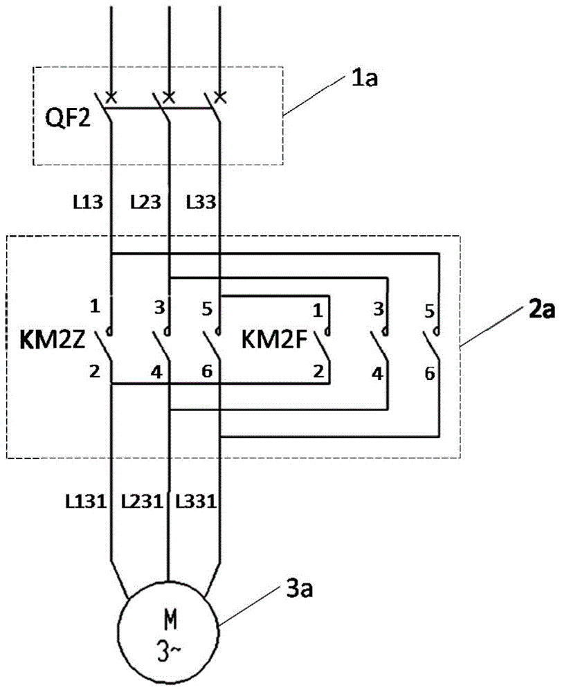
[0023] In the prior art, the motor-driven conveying belt movement generally adopts direct start. The circuit breaker 1a controls the connection or disconnection of the three-phase power supply. The contactor 2a controls the forward and reverse rotation of the motor 3a, and then directly connects with the three-phase motor 3a. Connection, this kind of control method has a large starting current at no-load and on-load, which interferes with other electrical equipment in the grid, and causes a large impact when the belt starts and stops. Therefore, a step-down starting device needs to be added to the control system to reduce the starting current, which will be described in detail below.

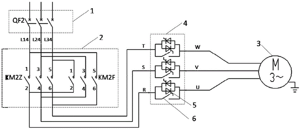
[0024] The invention provides a conveyor belt control device, such as image 3 As shown, it includes: the circuit breaker 1 and the contactor 2 connec...


PUM


Abstract

The invention relates to a conveyor belt control device comprising a circuit breaker and a contactor which are sequentially connected between a three-phase power supply and a conveyor belt motor. The circuit breaker can switch on or off the three-phase power supply. The contactor can make the conveyor belt motor rotate forwardly or reversely. A reduced-voltage starter capable of regulating the voltage in a stepless manner is connected between the contactor and the conveyor belt motor. According to the conveyor belt control device, the no-load and on-load starting currents are reduced, the impact on other equipment in a power grid is reduced, a conveyor belt is stable and small in impact when being started or stopped, and a dragging system shaft does not bear very large shear force. Through the optimization of the performances, the service life of the conveyor belt system is prolonged.

Description

Technical field [0001] The invention relates to the field of electrical control, in particular to a conveying belt control device. Background technique [0002] During the excavation construction, the operating arm of the excavating equipment digs the earth to the front end of the conveying device, and then the motor drives the conveying belt to transport it to the back end, and finally transports the earth to the transport trolley through the guide device. In the conveying device, the motor is connected to the conveying belt after being decelerated by the reducer to drive the conveying belt to run. [0003] At present, the motor that controls the conveyor belt mainly adopts a direct start method, such as figure 1 The electrical schematic shown and figure 2 As shown in the control process block diagram, the circuit breaker 1a controls the connection or disconnection of the three-phase power supply, and the contactor 2a controls the forward and reverse rotation of the motor 3a, and...

Claims


Application Information

Patent Timeline
Patent Type & Authority Applications(China)
IPC IPC(8): H02P1/28H02P1/40B65G43/00
Inventor 王伟路刚杜祥虎程红威
Owner 徐州徐工能源装备有限公司
Why Eureka
Try Eureka