Elevator device

A technology for elevators and control devices, applied in transportation, packaging, elevators, etc., can solve problems such as ear blockage of passengers, and achieve the effect of reducing usability

Active Publication Date: 2017-07-18
HITACHI LTD
View PDF1 Cites 0 Cited by
  • Summary
  • Abstract
  • Description
  • Claims
  • Application Information

AI Technical Summary

Problems solved by technology

[0003] However, in recent years, along with high-rise buildings, elevators have been increased in speed and length. In such elevators, sudden changes in air pressure occur due to the lifting and lowering of the car, causing the ears of passengers to be blocked. Ear plugging

Method used


Image

  • Elevator device
  • Elevator device
  • Elevator device

Examples


no. 1 approach

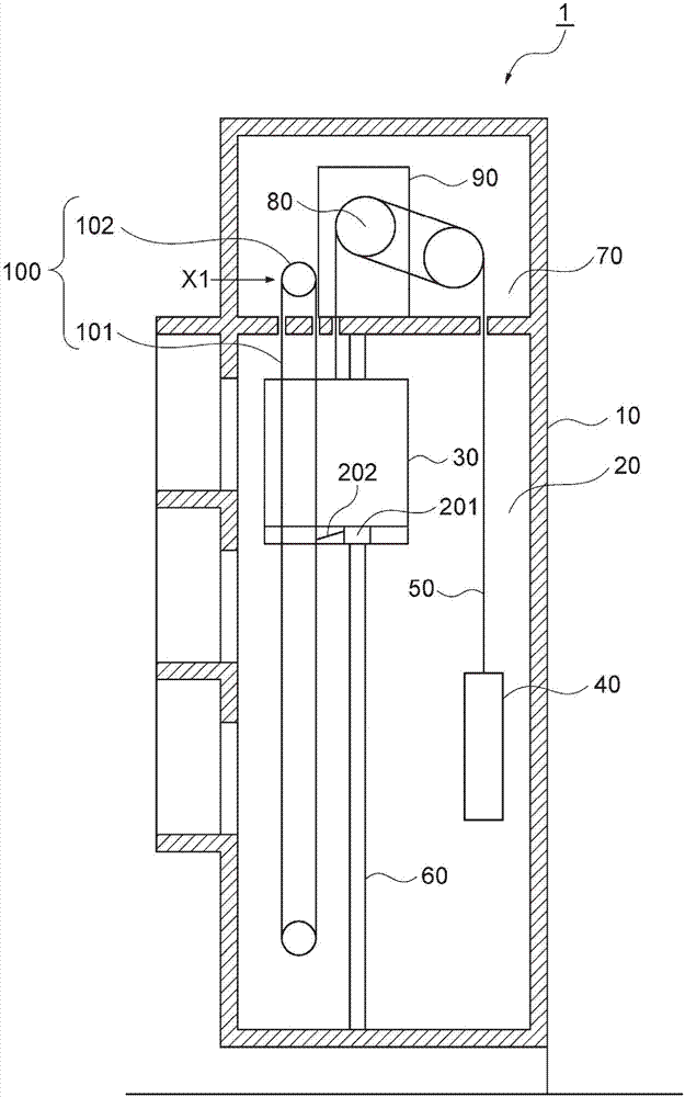
[0023] figure 1 The overall structure of the elevator apparatus 1 of this embodiment is shown. The elevator apparatus 1 is configured to connect a car 30 , which is an elevator body, and a counterweight 40 via main ropes 50 in an elevator passage 20 provided in a building 10 , and to enable the car 30 to ascend and descend along guide rails 60 .

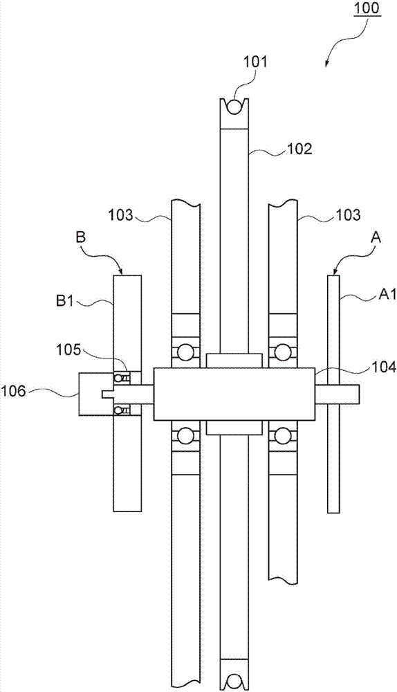
[0024] A hoist 80 around which the main rope 50 is wound, a control device 90 for controlling the hoist 80 , and a speed governor 100 are disposed in a machine room 70 formed on the upper portion of the lift passage 20 . The governor 100 is composed of an annular speed regulating rope 101 and a tow rope block 102, wherein the above-mentioned speed regulating rope 101 is arranged in the entire area of ​​the lifting stroke in the lifting passage 20, and the above-mentioned tow rope block 102 is arranged on the machine. chamber 70, and the rope 101 for speed regulation is hung in coils. exist figure 2 , the front structure of the go...

no. 2 approach

[0049] The second embodiment differs from the first embodiment in that the control device 90 causes the car 30 to ascend to the entrance floor when an abnormality is detected in the clutch 105 . In the second embodiment, configurations different from those in the first embodiment will be described.

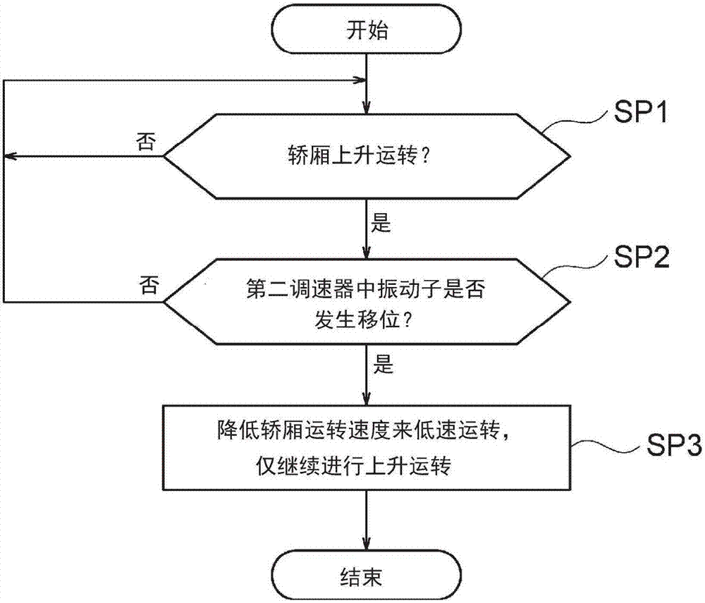
[0050] Figure 4 Shows the processing procedure of the second emergency operation processing. Due to the processing of step SP11 and step SP12 and the first emergency operation processing ( image 3 ) in steps SP1 and SP2 are the same, so the description here is omitted. When an affirmative result is obtained in the determination of step SP12, the control device 90 determines that an abnormality has occurred in the clutch 105 and executes the emergency operation.

[0051] As the emergency operation here, for example, the control device 90 lowers the operating speed of the car 30 to set it as a low-speed operation, and stops after operating to a pre-registered target floor (step...

no. 3 approach

[0055] The third embodiment differs from the first embodiment in that the control device 90 causes the car 30 to ascend to the nearest floor when an abnormality is detected in the clutch 105 . In the third embodiment, configurations different from those in the first embodiment will be described.

[0056] Figure 5 A processing procedure of the third emergency operation processing is shown. Due to the processing of step SP21 and step SP22 and the first emergency operation processing ( image 3 ) in steps SP1 and SP2 are the same, so the description here is omitted. When an affirmative result is obtained in the judgment of step SP22, the control device 90 judges that an abnormality has occurred in the clutch 105 and executes the emergency operation.

[0057] As the emergency operation here, for example, the control device 90 lowers the operating speed of the car 30 to set a low-speed operation, stops the operation after reaching the nearest floor (step SP13), and ends this pr...


PUM


Abstract

The present invention is an elevator device which is provided with: a car that ascends and descends in a hoistway; a control unit that exercises control over the operation of the car such that the ascent and descent speeds during an ascent operation and during a descent operation of the car are different; an encoder that detects the traveling direction of the car and outputs a detection signal indicating the traveling direction to the control unit; a first speed governor that detects the ascent overspeed of the car; and a second speed governor that detects the descent overspeed of the car, and in which a clutch transmits the rotational movement of a sheave to a rotation body of the second speed governor during the descent operation of the car, and releases the transmission of the rotational movement from the sheave to the second speed governor during the ascent operation of the car. The control unit determines, on the basis of the detection signal from the encoder and a detection signal detected in the second speed governor, whether the clutch is abnormal or not during the ascent operation of the car, and when determining that the clutch is abnormal, performs control such that the operation of the car is switched to an emergency operation. Consequently, the present invention achieves improvement in availability by particularly reducing confinement during the ascent operation while ensuring safety.

Description

technical field [0001] The present invention relates to an elevator installation. Background technique [0002] Elevator devices generally include a speed governor to monitor the lifting speed of the car (Japanese: かご) in real time. When the car falls into a specified overspeed state, the speed governor makes the car stop urgently. Specifically, when the lifting speed of the car exceeds the rated speed and reaches the first overspeed (usually 1.3 times the rated speed), the governor will control the power supply of the hoist that drives the car and the power of the hoist that controls the hoist. The power supply of the control unit is cut off respectively. In addition, when the descending speed of the car exceeds the first overspeed due to some reasons and reaches the second overspeed (usually about 1.4 times the rated speed), the governor will activate the emergency stop device installed on the car to make the The car comes to an emergency stop mechanically. [0003] How...

Claims


Application Information

Patent Timeline
Patent Type & Authority Patents(China)
IPC IPC(8): B66B5/02
CPCB66B5/0031B66B5/044
Inventor 中山徹也平野薰田中雄大岩本晃
Owner HITACHI LTD
Why Eureka
Try Eureka