Washing device
The technology of a washing device and a mounting plate is applied in the washing field, and can solve the problems of occupying a large axial height space, increasing the space occupied by a shoe washing machine, and reducing the washing space of the shoe washing machine, so as to improve washing efficiency, be suitable for popularization and use, significant effect
- Summary
- Abstract
- Description
- Claims
- Application Information
AI Technical Summary
Problems solved by technology
Method used
Image
Examples
Embodiment 1
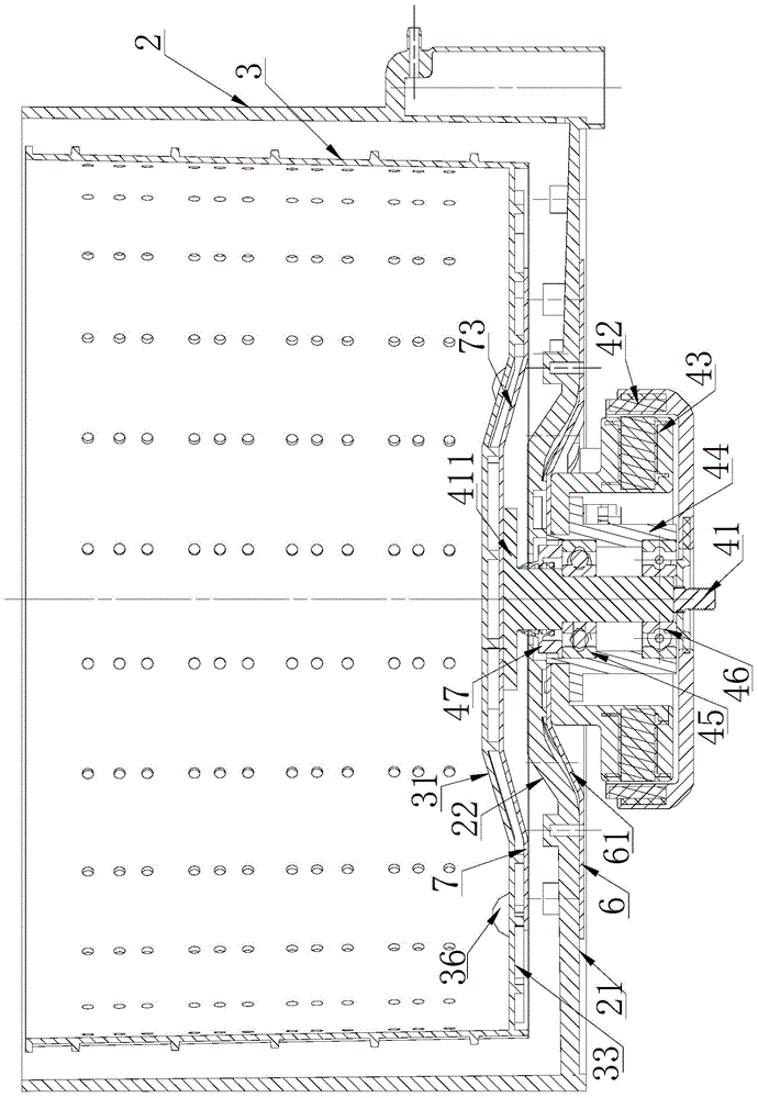
[0052] like image 3 and Figure 4 As shown, in this embodiment, the motor 4 includes a rotor 42 , a stator 43 , a bearing sleeve 44 , a bearing and an output shaft 41 . The rotor 42 includes a rotor body 421 covering the side wall of the stator 43 and a connecting portion 422 covering the lower side of the rotor body 421; the stator 43 includes an annular stator body 431 and the stator body 431 and the bearing sleeve. 44 is connected to the connecting portion 432. The bearing sleeve 44 includes a sleeve structure 441 provided in the hollow part of the stator for accommodating the bearing, and a flange 442 protruding from the outer side of the sleeve structure 441 and connected to the stator 43 . The output shaft 41 is arranged coaxially with the inner barrel 3, the output shaft 41 is fixedly installed in the bearing sleeve 44 through the bearing, the lower end of the output shaft 41 is connected with the rotor 42, and the upper end passes through the outer barrel bottom 21 ...
Embodiment 2
[0058] like image 3 and Figure 4 As shown, in this embodiment, the connecting portion 432 of the stator 43 is a rib 433 extending upward from the upper end of the stator body 431 . The part 434 is at least partially overlapped with the flange 442 of the bearing sleeve 44 , and the overlapping part of the bent part 434 and the flange 442 is connected by bolts to realize the fixed connection between the bearing sleeve 44 and the stator 43 . The connecting portion 432 and the flange 442 of the stator 43 are both disposed in the first groove 22 to reduce the overall height of the motor 4 and the outer tub 2 .
[0059] In this embodiment, the outer tub bottom 21 is connected with a mounting plate 6 . The center of the mounting plate 6 protrudes upward to form a first protruding portion 61 . The first protruding portion 61 of the mounting plate 6 is connected to the first groove 22 the lower wall in contact with each other. The first protruding portion 61 of the mounting plate ...
Embodiment 3
[0062] like Figure 5 and Image 6 As shown, in this embodiment, the connecting portion 432 of the stator 43 is a rib 433 extending horizontally from the inner wall of the body. Or the lower side surface is in contact with the flange 442 of the bearing sleeve 44 , so that the connecting parts 432 of the bearing sleeve 44 and the stator are all arranged in the hollow part of the motor stator body 431 . The stator body 431 is at least partially disposed in the first groove 22 to further reduce the overall height of the motor 4 and the outer tub 2 .
PUM
 Abstract
Description
Claims
Application Information
 - R&D
- Intellectual Property
- Life Sciences
- Materials
- Tech Scout
- Unparalleled Data Quality
- Higher Quality Content
- 60% Fewer Hallucinations
Browse by: Latest US Patents, China's latest patents, Technical Efficacy Thesaurus, Application Domain, Technology Topic, Popular Technical Reports.
© 2025 PatSnap. All rights reserved.Legal|Privacy policy|Modern Slavery Act Transparency Statement|Sitemap|About US| Contact US: help@patsnap.com


