Half-chute coupling joints for f-rails

A technology for connecting joints and rails, applied in the field of medium and low-speed maglev track structures, can solve the problems of limited lateral limit lifting, insufficient wheel stability, and location in gaps, etc., to prevent lateral dislocation, improve lateral limit capacity, and improve stability. sexual effect

Active Publication Date: 2018-01-26
CHINA RAILWAY SIYUAN SURVEY & DESIGN GRP
View PDF8 Cites 0 Cited by
  • Summary
  • Abstract
  • Description
  • Claims
  • Application Information

AI Technical Summary

Problems solved by technology

However, the above-mentioned connecting structure still has a limited limit on the lateral limit of the rail row. In particular, the flanges are set in a "step" shape so that some of the wheels will still be located in the gaps, resulting in insufficient stability of the wheels. Moreover, the above-mentioned stepped structure It is necessary to machine the complex shape of the end surface of the rail, and it is necessary to ensure that the contact surface dimensions of the guide rails at both ends are precisely matched. Difficulty, but also cause a huge waste of materials

Method used


Image

  • Half-chute coupling joints for f-rails
  • Half-chute coupling joints for f-rails
  • Half-chute coupling joints for f-rails

Examples


Embodiment Construction

[0033] In order to make the object, technical solution and advantages of the present invention clearer, the present invention will be further described in detail below in conjunction with the accompanying drawings and embodiments. It should be understood that the specific embodiments described here are only used to explain the present invention, not to limit the present invention. In addition, the technical features involved in the various embodiments of the present invention described below can be combined with each other as long as they do not constitute a conflict with each other.

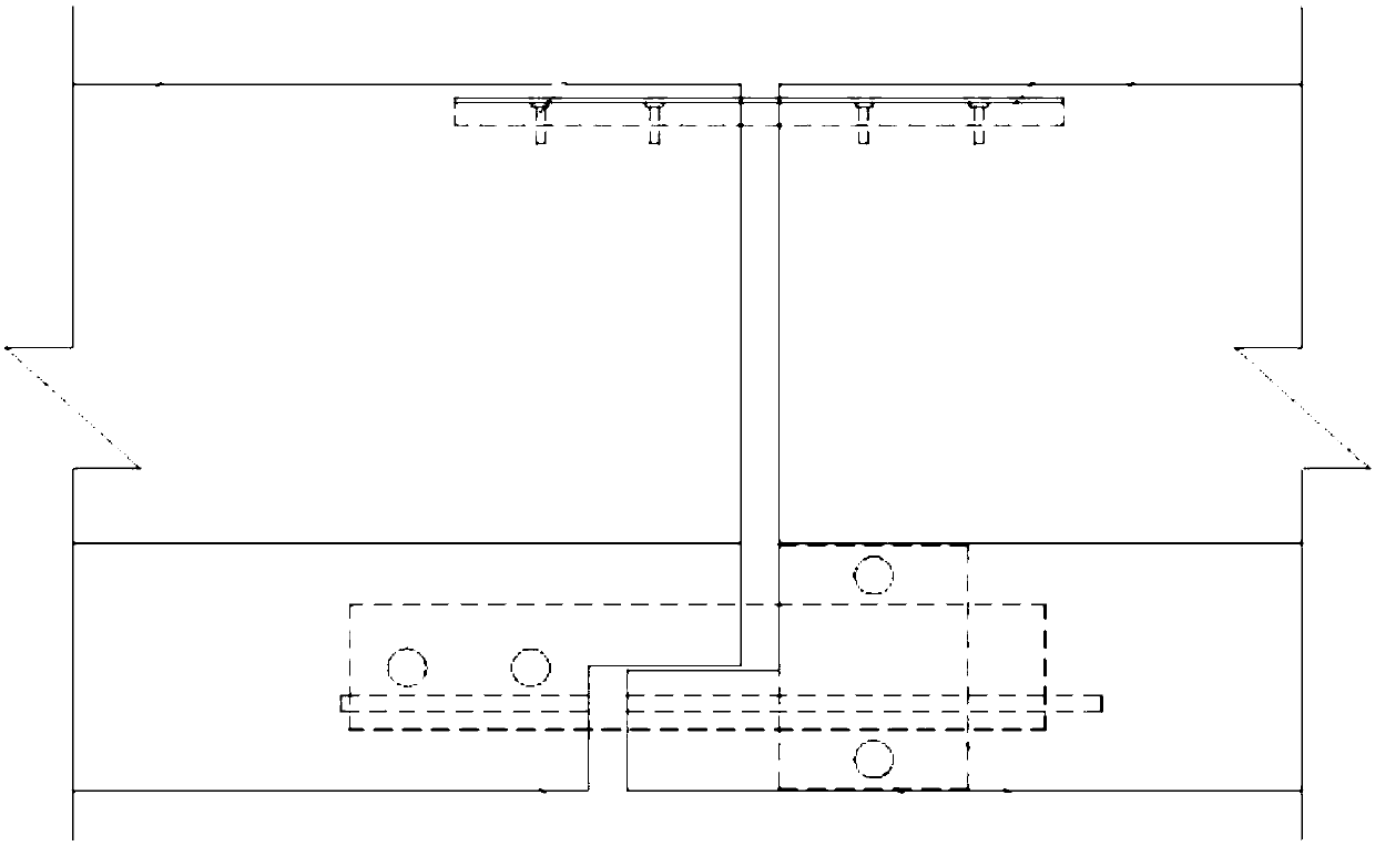
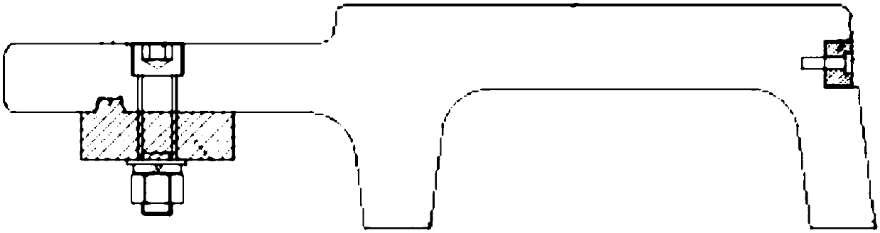
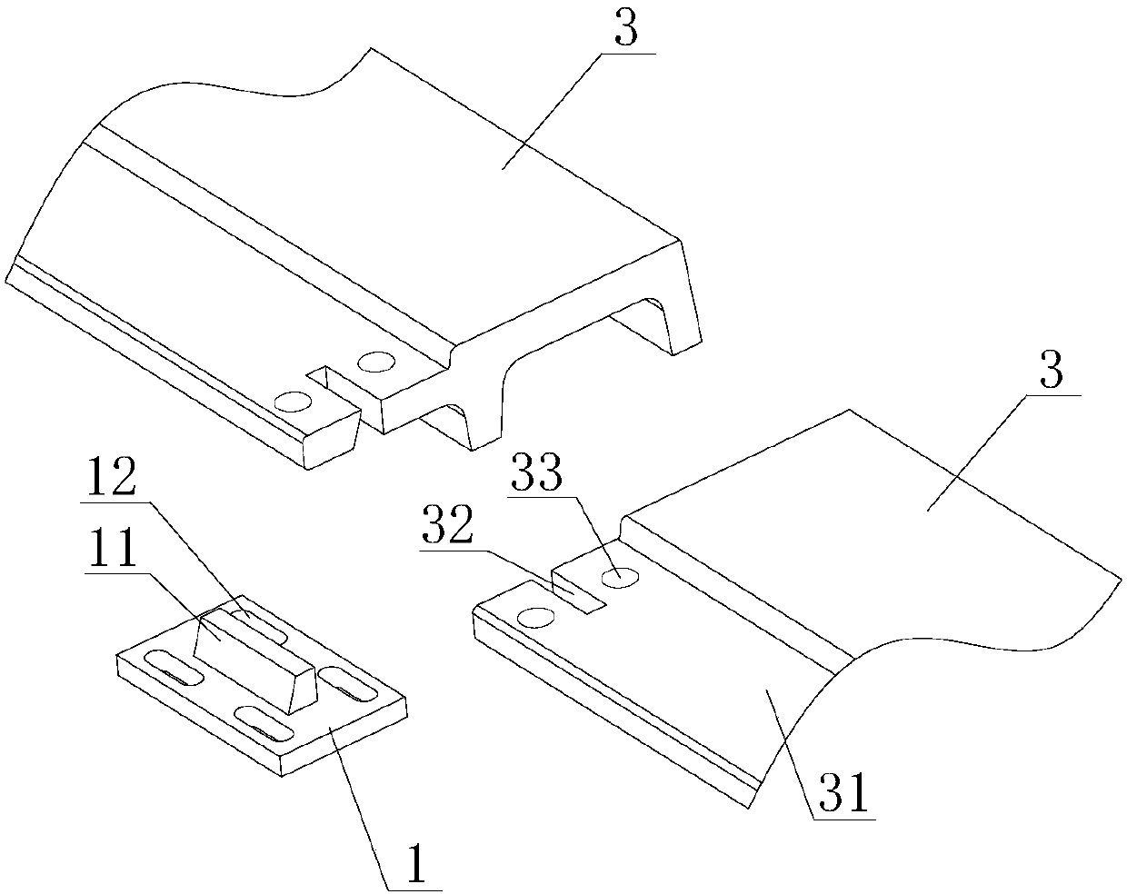
[0034] The connection joint according to one embodiment of the present invention is used for the connection of adjacent rail rows of a medium-low speed maglev system, especially the connection of F-shaped steel rails on two rail rows. In order to adapt to the expansion and deformation caused by the temperature change between the rail row and the lower foundation, an expansion joint is set betwee...


PUM


Abstract

The invention discloses a semi-chute type connector for an F-shaped steel rail.The connector comprises a lower connecting plate and a limiting boss.The limiting boss is arranged on one side face of the lower connecting plate.The surface of the protruding end of the limiting boss is a plane.Wing plates of the F-shaped steel rail are each correspondingly provided with a vertical-through groove matched with one end of the limiting boss.A long-strip-shaped gap formed by the through grooves of the two opposite wing plates and the gap between the two through grooves is used for allowing the limiting boss on the lower connecting plate to be inserted therein.Connecting pieces penetrate through connecting holes to fixedly connect the lower connecting piece with the wing plates, so that the limiting boss penetrates through the long-strip-shaped gap, the surface of the protruding end of the limiting boss is flush with the upper surfaces of the wing plates, the side face of the limiting boss makes complete contact with the inner walls of the through grooves in the wing plates, and then F-shaped steel rail connection is achieved.According to the connector, it can be ensured that a wheel is not disengaged from the wing plates all the time, impact of the rail gap on the walking wheel can be completely avoided, and meanwhile additional high-difficulty machining and strength or performance weakening do not need to be carried out on the structure of the F-shaped steel wing plates.

Description

technical field [0001] The invention belongs to the technical field of medium and low-speed magnetic levitation track structures, and in particular relates to a connection joint for F-shaped steel rails, which is suitable for the connection between rail rows of medium and low-speed magnetic levitation tracks. Background technique [0002] The medium and low-speed maglev rail transit adopts the suspension and guidance technology of the constant electromagnet suction type, and realizes the suspension and guidance of the vehicle through the electromagnetic attraction between the U-shaped electromagnet on the vehicle suspension frame and the F-shaped rail. At present, the structure of the medium and low speed maglev track mainly adopts the steel sleeper type. The track mainly includes induction plates, F-shaped steel rails (also called F rails), expansion joints, connectors and fasteners, steel sleepers, fastener systems, and bearings from top to bottom. It is composed of rail p...

Claims


Application Information

Patent Timeline
Patent Type & Authority Patents(China)
IPC IPC(8): E01B25/30
CPCE01B25/305
Inventor 李伟强孙立郭志勇靖仕元全顺喜娄会彬王森荣郜永杰
Owner CHINA RAILWAY SIYUAN SURVEY & DESIGN GRP
Why Eureka
Try Eureka