A bridge combined construction method

A construction method and combined technology, which is applied in bridges, bridge construction, erection/assembly of bridges, etc., can solve problems such as high cost, limited construction length, and influence of bridge force, so as to reduce the probability of carbonization and improve construction accuracy , Guarantee the effect of installation accuracy

Active Publication Date: 2017-05-24
郑卫忠 +1
View PDF6 Cites 0 Cited by
  • Summary
  • Abstract
  • Description
  • Claims
  • Application Information

AI Technical Summary

Problems solved by technology

The disadvantages are: the construction of the joints of the unit bodies constituting the bridge deck is troublesome, the connection strength of the joints between the unit bodies constituting the bridge deck is poor, leaving hidden dangers; the construction equipment requires high requirements, and bridges with large spans are not suitable for use
The disadvantages are: the passage or navigation under the bridge must be closed, which will cause obstacles to local traffic and economic development; the requirements for the terrain conditions under the bridge are relatively high, and the cost of bent-bench base treatment and bent-frame preloading is quite high; the sinking of the bent frame will cause quality problems. ACCIDENT
The disadvantages are: high construction requirements, low safety factor for cantilever construction; the construction length of each unit is limited, there are many construction units per span, and the amount of work for each unit is not large, but there are many construction procedures for each unit. It takes a long time to put the hanging basket in place, set up the formwork, bind the steel bars, pour concrete, maintain the concrete, demould, apply prestress, seal the anchor, and drop the frame, so the construction period is long and the progress is very slow; It is difficult to control the precision of the construction project, and when the closing error is large, it will affect the force of the bridge; the project cost is high
It can be seen that the existing bridge construction methods are difficult to combine prefabricated installation and on-site pouring at the same time, the construction method is single, and the cost is high

Method used


Image

  • A bridge combined construction method
  • A bridge combined construction method
  • A bridge combined construction method

Examples


Embodiment 1

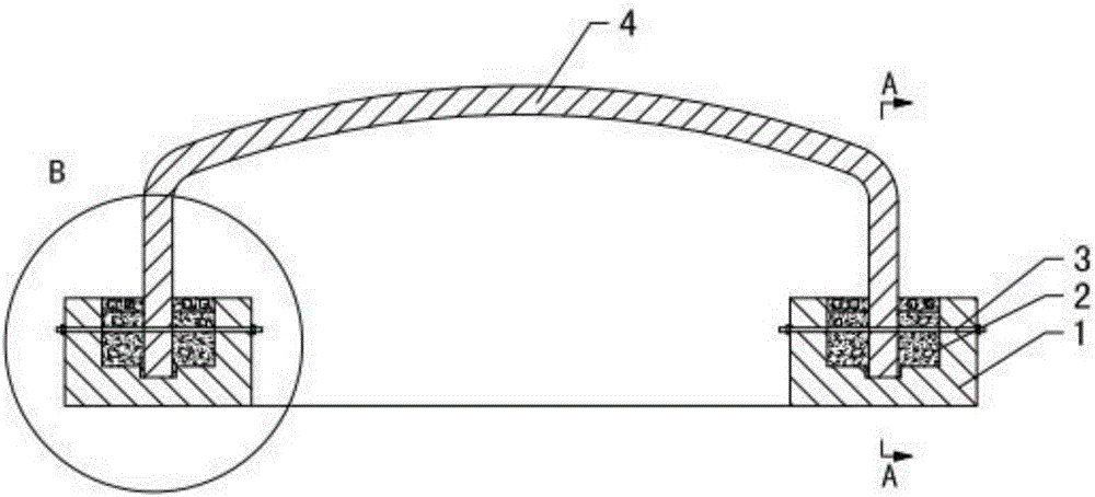
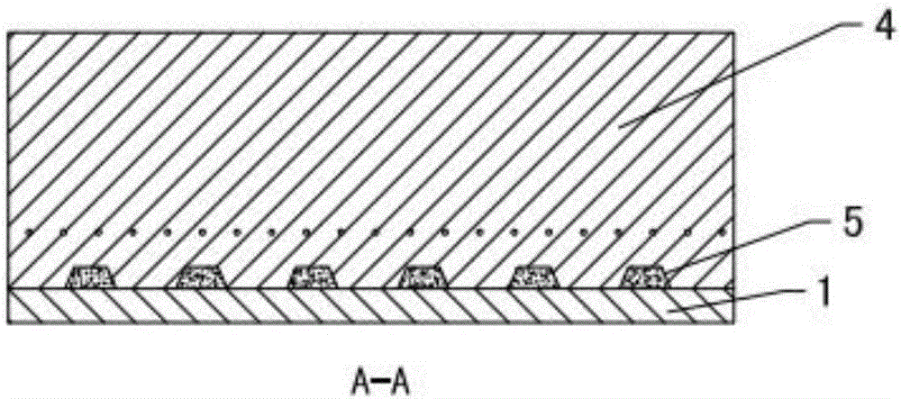
[0030] refer to Figure 1~3 , the combined bridge construction method comprises the following steps:

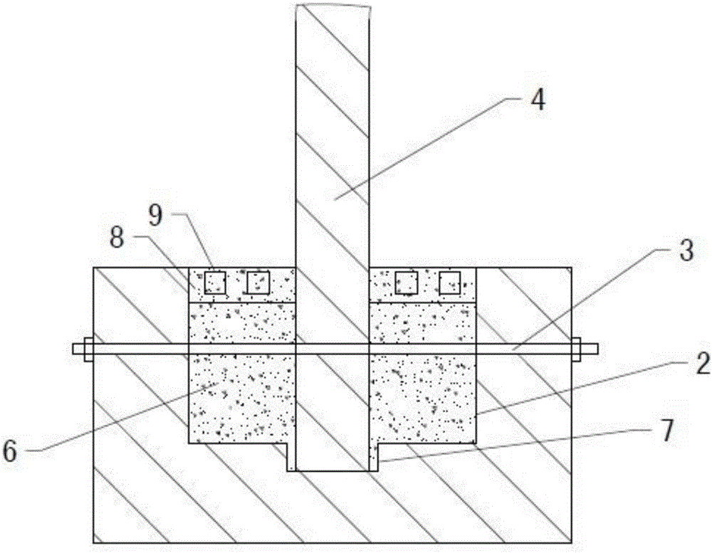
[0031] S1, making prefabricated parts: making the prefabricated parts of the base 1 and the bridge plate 4, the bridge plate 4 is arched, the upper side of the base 1 is provided with grooves 2 for accommodating the two ends of the bridge plate 4, and the two ends of the bridge plate 4 are provided with transverse The grout hole 5 and the bridge plate fixing hole, the base fixing holes corresponding to the bridge plate fixing holes are provided on the two side walls of the groove 2, and in the process of pouring concrete, the concrete passes through the grout hole 5 from the bridge plate 4 One side flows to the other side, and the concrete on both sides of the bridge plate 4 is connected as a whole through the grout holes 5, so that the bridge plate 4 is fixed more firmly. Furthermore, a positioning groove 7 is provided at the bottom of the groove 2, and the end of the bridg...

Embodiment 2

[0038] refer to Figure 4 , the vibrator used in this embodiment includes a housing 10 and a vibration generating device fixed in the housing 10, the side wall of the housing 10 is provided with a mortar inlet 12, the upper end of the housing 10 is provided with an exhaust port 17, and the lower end is provided with There are mortar outlets 15 . The mortar in the concrete enters the casing 10 through the mortar inlet 12, and the mortar undergoes gas-liquid separation in the casing 10. The mortar is discharged from the mortar outlet 15, and the air contained in the mortar is discharged upward from the exhaust port 17. One is to reduce the air in the mortar. Voids, prevent carbonation, and the second is to improve the strength of concrete.

[0039] Concrete, vibration generator comprises eccentric cylinder 13 and motor 16, and eccentric cylinder 13 is vertically arranged, and the wall thickness of both sides of eccentric cylinder 13 is different, and motor 16 is fixed on the up...

Embodiment 3

[0042] The combined bridge construction method comprises the following steps:

[0043] S1, making prefabricated parts: making the prefabricated parts of the base 1 and the bridge plate 4, the bridge plate 4 is arched, the upper side of the base 1 is provided with grooves 2 for accommodating the two ends of the bridge plate 4, and the two ends of the bridge plate 4 are provided with transverse The slurry passing hole 5 and the fixing hole of the bridge plate, the two side walls of the groove 2 are provided with base fixing holes corresponding to the fixing holes of the bridge plate.

[0044] S2, install the prefabricated parts: fix the base 1 at a predetermined position, hoist the bridge plate 4 to two adjacent bases 1, insert the end of the bridge plate 4 into the groove 2, and pass the fixing part 3 through the fixing hole of the bridge plate and the base fixing hole, and the two ends of the fixing part 3 are fixedly connected with the base 1.

[0045] S3, pouring concrete: ...


PUM


Abstract

The invention discloses a bridge combination type construction method. The construction method includes the following steps that S1, prefabricated members are manufactured, wherein the prefabricated members of bases and a bridge board are manufactured; S2, the prefabricated members are installed, wherein the bases are fixed to the preset positions, and the bridge board is lifted to the two adjacent bases; and S3, concrete is poured, wherein the concrete is poured into grooves in the two sides of the ends of the bridge board, concrete blocks with the volume ranging from 1000 cubic centimeters to 15000 cubic centimeters are added to the grooves while the concrete is poured, first concrete layers are formed in the grooves, multiple steel reinforcement cages are evenly placed on the upper sides of the first concrete layers, and the concrete is continuously poured to the upper sides of the first concrete layers to form second concrete layers. The sum of the volume of the concrete in all the steel reinforcement cages is 50% to 80% of the volume of the second concrete layers. By the adoption of the method, a prefabricating installation and cast-in-place combination method is adopted, a construction period is shortened, cost is low, and the strength of a bridge is high.

Description

technical field [0001] The invention discloses a bridge construction method, and in particular discloses a bridge combined construction method. Background technique [0002] Bridge construction methods, one is prefabricated installation construction, and the other is on-site pouring construction. There are two ways to fix the outer formwork for forming the bridge slab in the cast-in-place: one is to use the full hall bracket for support, and the other is to use the hanging basket for suspension. [0003] Prefabricated installation construction, bridge piers and bridge slabs can be constructed in parallel, and the construction period is relatively short; the bridge construction process has little impact on the traffic under the bridge. The disadvantages are: the construction of the joints of the unit bodies constituting the bridge deck is troublesome, the connection strength of the joints between the unit bodies constituting the bridge deck is poor, leaving hidden dangers; t...

Claims


Application Information

Patent Timeline
Patent Type & Authority Patents(China)
IPC IPC(8): E01D21/00
CPCE01D21/00
Inventor 刘东霞代卫东和学庆朱海丽毛艳敏高建薛永丰郑卫忠蒋利萍
Owner 郑卫忠
Why Eureka
Try Eureka