Locking mechanism for transmission device

A technology of locking mechanism and transmission device, applied in the direction of transmission device control, mechanical equipment, components with teeth, etc., can solve the problems of unstable locking, inaccurate locking position, fast enough locking, etc., and achieve the goal of locking Increased tightening speed, fast locking and high stability

Inactive Publication Date: 2016-06-01
董艳华
View PDF0 Cites 0 Cited by
  • Summary
  • Abstract
  • Description
  • Claims
  • Application Information

AI Technical Summary

Problems solved by technology

[0003] The purpose of the present invention is to solve the problems that the existing transmission device uses friction and pressure to lock, the locking is not fast enough, the locking position is inaccurate and the locking is unstable, and to provide a locking device for the transmission device. mechanism

Method used


Image

  • Locking mechanism for transmission device
  • Locking mechanism for transmission device

Examples


specific Embodiment approach 1

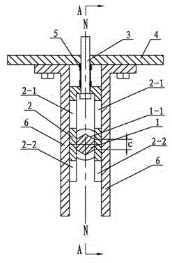
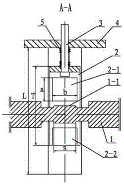
[0010] Specific embodiment one: in conjunction with Fig. 1 and figure 2 Describe this embodiment, this embodiment is that the locking mechanism of the transmission device includes a transmission shaft 1, an inverted U-shaped steel 2, a pull rod 3, an upper fixed plate 4, a spring 5 and two inverted L-shaped guide plates 6, and an inverted U-shaped steel 2 Each side wall on the top is provided with a through hole 2-1 and a groove 9-9 from the bottom end to the opening end, one end of the pull rod 3 is set in the U-shaped groove of the inverted U-shaped steel 2, and the other end of the pull rod 3 passes through The bottom plate, spring 5 and upper fixing plate 4 of the inverted U-shaped steel 2 are exposed outside the upper fixing plate 4, the middle part of the transmission shaft 1 is a hexagonal locking section 1-1, the transmission shaft 1 is horizontally arranged, and the hexagonal The locking section 1-1 is located in the U-shaped groove, the length s of the hexagonal lock...

specific Embodiment approach 2

[0011] Specific Embodiment 2: This embodiment is described with reference to FIG. 1 . The cross section of the hexagonal locking section 1-1 of this embodiment is a regular hexagon. This design can improve the stability of the hexagonal locking section 1-1 when it contacts the inner wall of the inverted U-shaped steel 2. Other components and connections are the same as those in the first embodiment.

specific Embodiment approach 3

[0012] Specific Embodiment Three: This embodiment is described in conjunction with FIG. 1. In this embodiment, the length c of each side on the regular hexagon of the hexagonal locking section 1-1 is less than the lower edge of the through hole 2-1 to the groove 9-9. distance above. This design makes the contact area between the hexagonal locking section 1-1 of the transmission shaft 1 and the side wall of the inverted U-shaped steel 2 large and stable. Other components and connections are the same as those in the second embodiment.

[0013] working principle:

[0014] When the transmission device needs to work, the inverted U-shaped steel 2 can be controlled to move up and down along the two inverted L-shaped guide plates 6 through the pull rod 3 and the spring 5, so that the hexagonal locking section 1-1 of the transmission shaft 1 is in the through hole 2- 1 or the groove 9-9, to realize the transmission of the transmission shaft l; when the transmission device needs to b...


PUM


Abstract

The invention relates to a locking mechanism, in particular to a locking mechanism for a transmission device. The problems that an existing transmission device is locked through friction and pressure, so that locking is not rapid, and the locking position is not accurate and not stable are solved. A through hole and a groove are formed in each side wall of inversed-U-shaped steel from the bottom end to the opening end, one end of a pull rod is arranged in a U-shaped groove of the inversed-U-shaped steel, and the other end of the pull rod penetrates a base plate, a spring and an upper fixing plate of the inversed-U-shaped steel to be exposed outside the upper fixing plate; a hexagonal locking section is arranged in the middle portion of a transmission shaft, the transmission shaft is horizontally arranged, the hexagonal locking section is located in the U-shaped groove, the length s of the hexagonal locking section is smaller than the width b of the through holes, and the diameter of a circumscribed circle of the hexagonal locking section is smaller than the length a of the through holes; two inversed-L-shaped guide plates are symmetrically arranged on the two sides of the inversed-U-shaped steel, a long-edge plate of each inversed-L-shaped guide plate is in contact with the adjacent side wall of the inversed-U-shaped steel, and a short-edge plate of each inversed-L-shaped guide plate is connected with the upper fixing plate through a connecting element. The locking mechanism is used for the transmission device.

Description

technical field [0001] The invention relates to a locking mechanism, in particular to a locking mechanism used on a transmission device. Background technique [0002] With the rapid development of machinery-related industries such as automobiles, construction, medical treatment, and machining, people have higher and higher requirements for the locking mechanism of the transmission system. It is difficult for traditional locking devices to meet the current high requirements for locking devices. At present, the widely used principle of locking mechanism is friction and pressure. The application of friction or pressure to lock the transmission device inevitably has disadvantages such as insufficient fast locking, inaccurate locking position and unstable locking. Contents of the invention [0003] The purpose of the present invention is to solve the problems that the existing transmission device uses friction and pressure to lock, the locking is not fast enough, the locking po...

Claims


Application Information

Patent Timeline
Patent Type & Authority Applications(China)
IPC IPC(8): F16H63/34
Inventor 董艳华
Owner 董艳华
Why Eureka
Try Eureka