Supercharge Your Innovation With Domain-Expert AI Agents!

Adjusting method for consistency between laser radar azimuth axis and optical axis

A technology of laser radar and adjustment method, applied in radio wave measurement systems, instruments, etc., can solve problems such as consistency adjustment of invisible optical axis and mechanical axis

Active Publication Date: 2016-06-01
BEIJING AEROSPACE INST FOR METROLOGY & MEASUREMENT TECH +1
View PDF5 Cites 11 Cited by
  • Summary
  • Abstract
  • Description
  • Claims
  • Application Information

AI Technical Summary

Problems solved by technology

[0004] The purpose of the present invention is to solve the problem of the consistency adjustment of the invisible optical axis and the mechanical axis, and provide a method for adjusting the consistency of the laser radar azimuth axis and the optical axis

Method used


Image

  • Adjusting method for consistency between laser radar azimuth axis and optical axis
  • Adjusting method for consistency between laser radar azimuth axis and optical axis
  • Adjusting method for consistency between laser radar azimuth axis and optical axis

Examples


Embodiment Construction

[0043] A method for adjusting the consistency between the azimuth axis and the optical axis of the laser radar according to the present invention is introduced below in conjunction with the accompanying drawings and embodiments:

[0044] Such as figure 1 As shown, a laser radar azimuth axis and optical axis consistency adjustment method includes the following steps:

[0045] The first step: build a stable working platform;

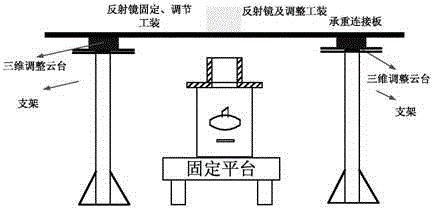
[0046] Build a stable working platform. In this example, if figure 2As shown, the stable working platform includes a fixed platform, a bracket, a three-dimensional adjustment pan-tilt, a support plate, a reflector and an adjustment tooling. Wherein, the fixed platform is used to ensure that the device to be installed and adjusted will not be affected by external vibrations during the installation and adjustment process. In this embodiment, a general-purpose precision optical platform is used for realization. There are two brackets, both of which are m...


PUM


Abstract

The invention belongs to the field of engineering measurement technology, and particularly to an adjusting method for consistency between a laser radar azimuth axis and an optical axis. The adjusting method aims to settle a problem of consistency adjustment between an invisible optical axis and a mechanical axis. The adjusting method comprises five steps, namely building a stable working platform, establishing a visible mounting and adjusting reference, performing consistency adjustment on an azimuth mechanical rotating axis and the visible mounting and adjusting reference, performing consistency adjustment between a receiving optical axis and the visible mounting and adjusting reference, and performing consistency adjustment between a transmitting optical axis and the visible mounting and adjusting reference. According to the adjusting method, through the steps of building the stable working platform, establishing the visible mounting and adjusting reference, performing consistency adjustment on the azimuth mechanical rotating axis and the visible mounting and adjusting reference, performing consistency adjustment between the receiving optical axis and the visible mounting and adjusting reference, and performing consistency adjustment between the transmitting optical axis and the visible mounting and adjusting reference, coaxiality between the visible mounting and adjusting reference and the azimuth axis is realized; and furthermore the visible mounting and adjusting reference is coaxial with the transmitting optical axis and the receiving optical axis. Therefore the azimuth axis is coaxial with the transmitting optical axis and the receiving optical axis, namely consistency adjustment between the azimuth axis and the optical axis is finished.

Description

technical field [0001] The invention belongs to the technical field of engineering measurement, and in particular relates to a method for adjusting the consistency of a laser radar azimuth axis and an optical axis. Background technique [0002] Laser three-dimensional measurement system is widely used in the field of space target relative attitude measurement. In the design and manufacture of the laser three-dimensional measurement system, the consistency adjustment of the azimuth axis of the two-dimensional turntable and the optical axis of the receiving / transmitting optical path is a key part of the entire assembly process. The laser measurement system emits a laser beam through the azimuth axis of the two-dimensional turntable, and is reflected by the mirror on the pitch axis. In space, it is emitted back by the target surface cube mirror for measurement. During the measurement process, the control beam moves with the target to obtain the dynamic motion coordinates of a ...

Claims


Application Information

Patent Timeline
Patent Type & Authority Applications(China)
IPC IPC(8): G01S7/497
Inventor 董利军刘柯梁雅军缪寅宵郭磊高越
Owner BEIJING AEROSPACE INST FOR METROLOGY & MEASUREMENT TECH
Features
  • R&D
  • Intellectual Property
  • Life Sciences
  • Materials
  • Tech Scout
  • Unparalleled Data Quality
  • Higher Quality Content
  • 60% Fewer Hallucinations
Learn More