Obstacle region division method based on minimum enclosing circle and maximum inscribed circle

A technology of obstacle area division and maximum inscribed circle, applied in non-electric variable control, instruments, control/regulation systems, etc., can solve problems such as the inability to give a planable track area

Active Publication Date: 2016-06-01
UNIV OF ELECTRONICS SCI & TECH OF CHINA
View PDF5 Cites 32 Cited by
  • Summary
  • Abstract
  • Description
  • Claims
  • Application Information

AI Technical Summary

Problems solved by technology

Therefore in the present invention emphatically solves following basic problem:
[0019] 2. Provide a method for quickly judging obstacles, and solve the problem that existing methods cannot give a planable track area;

Method used


Image

  • Obstacle region division method based on minimum enclosing circle and maximum inscribed circle
  • Obstacle region division method based on minimum enclosing circle and maximum inscribed circle
  • Obstacle region division method based on minimum enclosing circle and maximum inscribed circle

Examples


Embodiment Construction

[0055] All features disclosed in this specification, or steps in all methods or processes disclosed, may be combined in any manner, except for mutually exclusive features and / or steps.

[0056] Granularized obstacle description framework

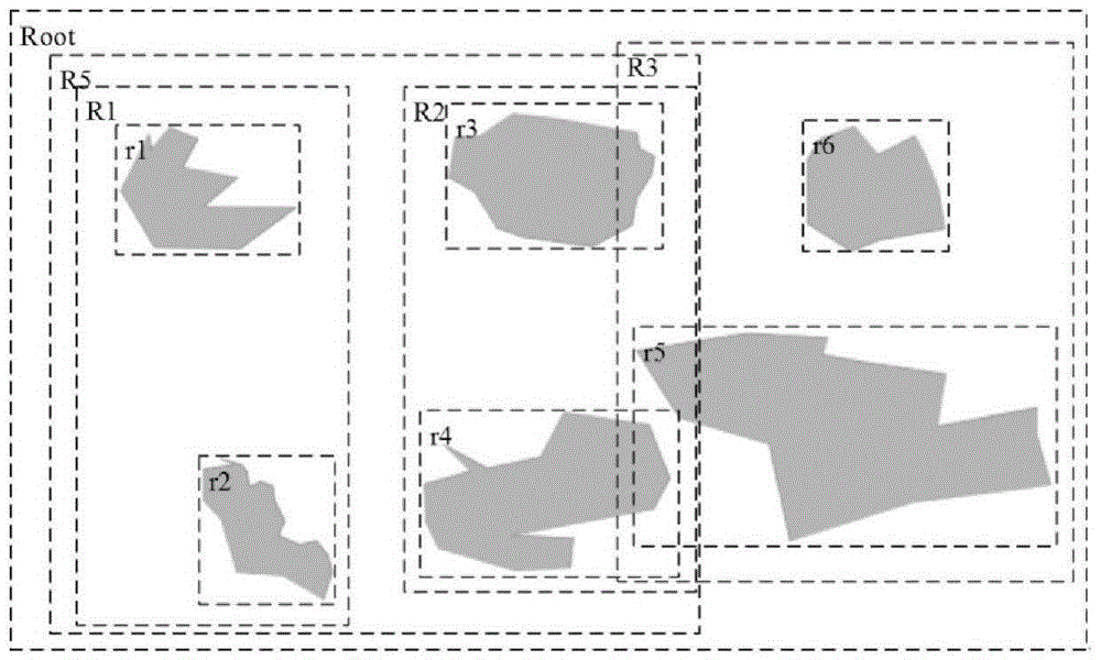
[0057] In the present invention, by analyzing the basic characteristics and existing characteristics of environmental barriers, we design a multi-grained structure of barriers such as Figure 4 shown. Divided according to different granularities, one obstacle can be divided into 1, 2, 3,..., N obstacle areas (sub-areas). The division of sub-regions needs to be determined according to the corresponding path planning algorithm, which is not included in the obstacle description method of this patent.

[0058] This multi-granularized obstacle description framework provides support for obstacle path planning at different granularities:

[0059] The aircraft quickly flies over obstacles or avoids high-threat obstacles. It only needs to know whe...


PUM


Abstract

An obstacle region division method based on a minimum enclosing circle and a maximum inscribed circle includes the following steps of: obtaining a maximum steering curve of a moving object according to the speed and the direction of the moving object; loading m obstacle regions of a map, dividing the obstacle regions into N sub-regions according to an initial programming granularity N, and generating the minimum enclosing circle and the maximum inscribed circle for each sub-region; drawing tangent lines on the two types of circles from the current position of the moving object, respectively defining the regions enclosed by the tangent lines as current forbidden regions and current limitation regions with each number of m*N, then respectively taking union and obtaining a current total forbidden region and a current total limitation region, and defining the regions except the two regions as safe regions; judging whether the maximum steering curve of the moving object and the tangent lines of the two types of circles have intersection points, and judging whether the granularity N is needed to increase according to the obstacle threat degree; for high threat degree obstacle, only allowing programme in the safe regions, and for a general threat degree obstacle, allowing programme in part limitation regions and safe regions; and outputting the region division of a current total programming region, the current total limitation region and the current total forbidden region.

Description

technical field [0001] The invention relates to a multi-granularity representation method for obstacles in the path planning of a fixed-wing aircraft and a design for the method used in the path planning. Background technique [0002] In aircraft path planning, obstacles in the environment are the main objects of path planning, and an effective obstacle representation method will simplify the path planning of the aircraft and improve the overall performance of path planning. However, in the current research, most of the attention is focused on the research of path planning algorithm (scheme), and the processing of the flight environment is often very simple, and there is no effective method or mode for the path planning of the aircraft. to model or describe environmental obstacles. The main features of the current research are summarized as follows: [0003] There is no specific representation and description of obstacles, and the planning area is only marked as a feasible...

Claims


Application Information

Patent Timeline
Patent Type & Authority Applications(China)
IPC IPC(8): G05D1/10
CPCG05D1/101
Inventor 徐杨刘铭李畅李燕
Owner UNIV OF ELECTRONICS SCI & TECH OF CHINA
Why Eureka
Try Eureka