An Adaptive Installation Error Slip Ring Connecting Device

A connection device and installation error technology, which is applied to the two-part connection device, the parts of the connection device, and the connection, can solve problems such as poor workmanship, hidden dangers of interference, and damage to the structure of the confluence ring, and achieve the requirements of reducing parallelism and improving Manufacturability, the effect of reducing requirements

Active Publication Date: 2018-09-25
SHANGHAI INST OF ELECTROMECHANICAL ENG
View PDF3 Cites 0 Cited by
  • Summary
  • Abstract
  • Description
  • Claims
  • Application Information

AI Technical Summary

Problems solved by technology

[0002] At present, the foreign exchange ring and the rotary body at home and abroad generally adopt the connection form of shift forks and grooves, which requires high precision for the distance, parallelism, and concentricity of the transfer ring and the rotary body, and the manufacturability is poor.
[0003] The distance error will easily cause the extrusion or loosening of the shift fork and the groove, the angle error will cause the hidden danger of interference during the rotation process, and the serious eccentricity error will also lead to the destruction of the structure of the collector ring

Method used


Image

  • An Adaptive Installation Error Slip Ring Connecting Device
  • An Adaptive Installation Error Slip Ring Connecting Device
  • An Adaptive Installation Error Slip Ring Connecting Device

Examples


Embodiment Construction

[0015] In order to describe the technical content, structural features, objectives and effects of the present invention in detail, the present invention will be further described below in conjunction with the accompanying drawings and embodiments.

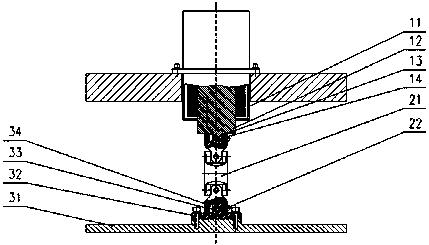
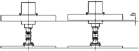
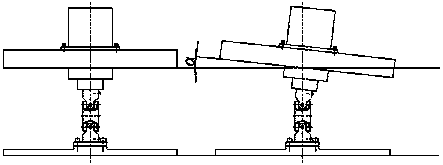
[0016] see Figure 1 to Figure 4 , the present invention is an adaptive installation error slip ring connection device, including slip ring, universal joint, and rotary body. The slip ring includes a slip ring shell 11, a slip ring rotor shaft end 12, a keyway 13, and a key 14, and the slip ring rotor shaft end 12 is φ20×17. The universal joint includes a double precision universal joint 21 and a set screw 22 . The revolving body includes a revolving body 31, a revolving body shaft end 32, a keyway A33, and a key A34, and the revolving body shaft end 32 is φ20×17. Key 14 and key A34 are GB / T1096-2003 key 6×16, set screw 22 is M4×15, and the assembly relationship between slip ring housing 11 and slip ring rotor shaft end 12 is the...


PUM


Abstract

The invention discloses a collector ring connection device adapted to installation errors by itself. The device comprises a collector ring, a universal joint and a revolving unit. The collector ring comprises a collector ring housing, a collector ring rotor shaft end, a keyway and a key. The collector ring rotor shaft end is connected with the universal joint through the keyway and the key. The universal joint is a two-section tight universal joint. A screw hole is formed in the upper section and lower section of the universal joint respectively. Two fastening screws are used to lock the collector ring rotor shaft end and the universal joint, and the revolving unit shaft end and the universal joint respectively. The revolving unit comprises a revolving body, a revolving unit shaft end, a keyway A and a key A. The revolving unit shaft end is a part of the revolving unit and is threaded with the revolving body, and is connected with the universal joint by the keyway A and the key A. By adjusting the fastening screws on the upper and lower sections of the universal joint, the distance error between the collector ring and the revolving unit can be compensated effectively, and by means of the deformation of the two-section tight universal joint itself, the angle error and the eccentricity error between the collector ring and the two-section tight unit can be compensated effectively.

Description

technical field [0001] The invention relates to the technical field of slip rings, in particular to a connection device for slip rings. Background technique [0002] At present, the foreign exchange ring and the rotary body at home and abroad generally adopt the connection form of shifting forks and grooves, which requires high precision for the distance, parallelism, and concentricity of rotation between the confluence ring and the rotary body, and poor manufacturability. [0003] The distance error will easily cause the extrusion or loosening of the shift fork and the groove, the angle error will cause the hidden danger of interference during the rotation process, and the severe eccentricity error will also lead to the destruction of the structure of the slip ring. [0004] Therefore, the industry needs a slip ring connection device that is self-adaptive to installation errors. Contents of the invention [0005] The present invention solves the problem of connection bet...

Claims


Application Information

Patent Timeline
Patent Type & Authority Patents(China)
IPC IPC(8): H01R24/00H01R31/06H01R13/631
Inventor 吕文波鲁勇军孙刚戴铮王良敏周元春史松伟张昶邹波彭永红齐可鑫张志国
Owner SHANGHAI INST OF ELECTROMECHANICAL ENG
Why Eureka
Try Eureka