a dishwasher

A dishwasher and washing tub technology, which is applied in the washing machine/washing machine for tableware, parts of the washing machine/rinsing machine for tableware, cleaning equipment, etc., can solve the corrosion of the rotating shaft, increase the manufacturing cost of the dishwasher, and the pressure deviation and other problems, to achieve the effect of reducing the requirements for production and assembly, avoiding local rapid aging, and improving manufacturing efficiency

Active Publication Date: 2018-01-05
宁波市安通机械有限公司
View PDF6 Cites 0 Cited by
  • Summary
  • Abstract
  • Description
  • Claims
  • Application Information

AI Technical Summary

Problems solved by technology

[0006] The disadvantage of the prior art is that: when multiple sets of guide rail mechanisms need to be set between the washing bucket lid and the washing bucket to complete the capping operation, as the working time increases gradually, the elastic force of the pressure spring will change differently, resulting in The pressure maintained by each group of guide rail mechanisms deviates, resulting in deviations in the seal between the washing bucket cover and the washing bucket, resulting in leakage of water and steam in the washing bucket, and the leaked water and steam will cause corrosion of the pressure spring and other components. Thereby accelerating the failure of the seal or the damage of other parts; it may also cause the corrosion of the rotating shaft to further affect the sealing effect or the separation of the washing bucket cover and the washing bucket; in addition, the setting of the rotating shaft also increases the complexity of the guide rail mechanism and reduces the operating efficiency of the guide rail mechanism. reliability, and increases the manufacturing cost of dishwashers

Method used


Image

  • a dishwasher
  • a dishwasher
  • a dishwasher

Examples


Embodiment Construction

[0029] A specific embodiment of the present invention will be described in detail below in conjunction with the accompanying drawings, but it should be understood that the protection scope of the present invention is not limited by the specific embodiment.

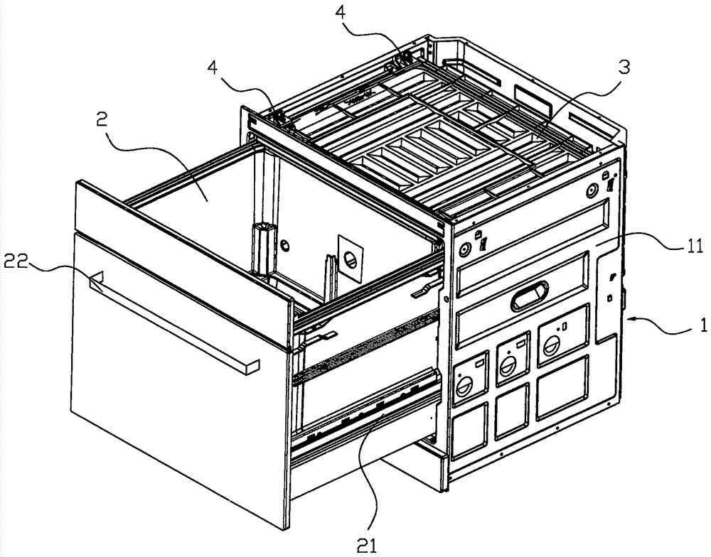
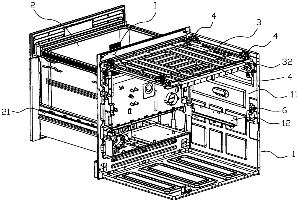
[0030] A kind of dishwasher of the present invention such as Figure 1-6 As shown, it includes: box body 1, washing bucket 2, washing bucket 2 is installed in the box body 1, there is a slide rail between the washing bucket 2 and the box body 1, and the slide rail 12 on one side of the box body 1 is installed in the box body On the side plate 11, the washing bucket slide rail 21 is installed on the outer surface of the two side walls of the washing bucket 2, and the handle 22 on the front outer surface of the washing bucket is pulled or pushed, and the slide rail 12 and the washing bucket slide rail 21 slide relative to each other, and the washing bucket 2 Slide into the box body 1 or slide out of the box body 1 along the ...


PUM


Abstract

The invention discloses a dish washing machine which comprises a box body and a washing bucket, wherein the washing bucket is mounted inside the box body; sliding tracks are arranged between the washing bucket and the box body; the washing bucket slides into the box body or out of the box body along the sliding tracks; the washing bucket is provided with a corresponding washing cover; the washing bucket cover covers the upper end hole of the washing bucket when the washing bucket slides into the box body in a set position; guide track mechanisms are arranged on two sides between the washing bucket cover and the box body in the sliding direction of the washing bucket; the guide track mechanisms comprise guide tracks and guide columns; the guide tracks consist of stripy guide holes or guide grooves; the guide tracks are arranged from high to low in the direction that the washing bucket slides into the box body; the guide columns are embedded into the guide tracks and move along the guide tracks; the guide tracks are fixedly connected with the washing bucket cover; the guide columns are fixedly connected with the box body. As the guide tracks are fixedly connected with the washing bucket cover, and the guide columns are fixed with the box body, the guide track mechanisms are simple and stable, the sealing effect of the washing bucket cover to the washing bucket can be ensured, and moreover the phenomenon that the sealing effect is failed because of unbalance connection in the long-term use process can be avoided.

Description

technical field [0001] The invention relates to a cleaning tool for tableware, in particular to a dishwasher. Background technique [0002] Dishwasher is a commonly used tableware cleaning equipment, which usually includes a side-opening door structure and a drawer structure; the drawer structure consists of a washing tub and slide rails, and the washing tub can be pulled out of the dishwasher cabinet along the slide rails Or slide in, the port of the washing tub faces up, and the objects to be cleaned are placed from the top to the bottom of the port of the washing tub, which makes it easy for the objects to be cleaned to be placed in the washing tub and arranged, so the drawer dishwasher becomes a dishwasher. main structural form. [0003] The washing bucket also includes a washing bucket cover, and the washing bucket cover closes the port of the washing bucket when the washing bucket is in the cleaning state, so as to prevent the water or water vapor in the washing bucke...

Claims


Application Information

Patent Timeline
Patent Type & Authority Patents(China)
IPC IPC(8): A47L15/02A47L15/42
CPCA47L15/02A47L15/4261
Inventor 童伟义
Owner 宁波市安通机械有限公司
Why Eureka
Try Eureka