Novel oil-gas well filling system and application method of same

A technology for oil and gas wells and wellbore, which is used in earth-moving drilling, wellbore/well components, and production fluids, etc. It can solve problems such as failure to achieve, failure of semi-permeable sealing and flow control technology, and inability to run liquid expansion packers. problems, to achieve the effect of improving the success rate

Active Publication Date: 2014-07-16
ANTON BAILIN OILFIELD TECH (BEIJING) CO LTD
View PDF7 Cites 4 Cited by
  • Summary
  • Abstract
  • Description
  • Claims
  • Application Information

AI Technical Summary

Problems solved by technology

[0015] (4) The downhole tubing string is deformed, but the deformation does not affect the entry of the flow control filter into the well, but the fluid-swellable packer cannot be run in
In this way, an effective axial packing ring cannot be formed; resulting in the failure of the semi-permeable packing ring, the purpose of the semi-permeable packing ring is to axially isolate the production section of the oil and gas well into many relatively independent production intervals, which cannot be realized. The overall failure of semi-permeable sealing and flow control technology

Method used


Image

  • Novel oil-gas well filling system and application method of same
  • Novel oil-gas well filling system and application method of same
  • Novel oil-gas well filling system and application method of same

Examples


Embodiment 1

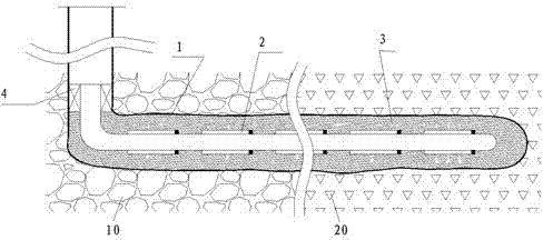
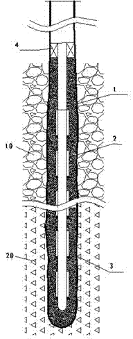
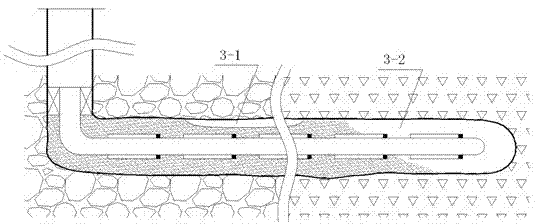
[0105] Such as Figure 5 As shown, the present invention provides a new oil and gas well filling system. The oil and gas well filling system includes the well wall of the oil and gas well and the well entry string that is lowered into the oil and gas well. Tube string for filter 5-2. An annulus is formed between the well entry pipe string and the well wall; at least one controllable circulation device 5-1 is arranged on the well entry pipe string.

[0106] The controllable circulation device is installed on the entry pipe string at the most toe end of the oil and gas well.

[0107] The controllable flow device has two states:

[0108] (1) Open state: during the initial filling, the controllable circulation device is in the open state, so that a certain amount of fluid carrying filling particles can be guided to the position of the controllable flow device, that is, the toe end of the oil and gas well; (2) Closed state:

[0109] The main part of a new oil and gas well fillin...

Embodiment 2

[0120] The main part of a new oil and gas well filling system includes:

[0121] (1) Controllable flow device: The controllable flow device is composed of a particle interceptor and a flow channel; for example Figure 12 as shown, Figure 12 The particle interceptor is composed of a sleeve 12-1, and the flow channel is a hole 12-2 with a designed flow rate arranged on the base pipe.

[0122] The particle interceptor is composed of a seam cover, the seam width is 0.5mm, Figure 12 Among them, 12-2 is the designed flow channel on the base pipe. A controllable flow device is assembled at the toe end of the entry pipe string corresponding to the oil and gas well.

[0123] (2) Intercepted particles: the specific gravity of the particles is 1.0g / cm 3 , solid round particles with an average particle size of 0.4mm, the largest particle size is about 0.6mm, and the smallest particle size is about 0.2mm.

[0124] (3) Filling particles: the specific gravity is 1.0g / cm 3 , round sol...

Embodiment 3

[0133] The main part of a new oil and gas well filling system includes:

[0134] (1) Controllable flow device: The controllable flow device is composed of a particle interceptor and a flow channel; for example Figure 13 As shown, the particle interceptor is composed of a slit sleeve with a slit width of about 0.5mm, and the circulation channel is a deep hole 13-2 arranged inside the base pipe.

[0135] Such as Figure 13 As shown, deep holes 13-2 are arranged inside the base pipe , A controllable flow device is assembled at the toe end of the entry pipe string corresponding to the oil and gas well.

[0136] (2) Intercepted particles: the specific gravity of the particles is 1.0g / cm 3 , solid round particles with an average particle size of 0.4mm, the largest particle size is about 0.6mm, and the smallest particle size is about 0.2mm.

[0137] (3) Filling particles: the specific gravity is 1.05g / cm 3 , round solid particles with an average particle size of 0.15 mm. Block...


PUM


Abstract

The invention discloses a novel oil-gas well filling system and an application method of the system. The oil-gas well filling system comprises an oil-gas well wall and a well-in pipe string put into an oil-gas well, wherein the well-in pipe string and the well wall form a ring space, and the well-in pipe string is provided with at least one circulation-controllable device. By using the novel oil-gas well filling system, a compact and complete half-penetrative seal baffling ring can be achieved in a whole oil-gas well. The method specifically comprises the phases of: 1, opening the circulation-controllable device, and forming a filling grain sand bed; 2, closing the circulation-controllable device; 3, completely building a half-penetrative seal baffling ring. The novel oil-gas well filling system facilitates building of the compact and complete half-penetrative seal baffle ring under the condition that flow-controlling filter pipe columns are placed, improving success rate of building of the half-penetrative seal baffling ring, and thus achieving the seal and baffling effect required by a half-penetrative seal baffling flow-controlling technology.

Description

[0001] technical field [0002] The invention relates to a new oil and gas well filling system and an application method of the system, belonging to the field of oil and natural gas exploitation. Oil and gas wells here refer to production wells in the broad sense of oil and gas field development, including oil wells, gas wells, natural gas wells, injection wells, steam injection thermal recovery wells, steam huff and puff wells, steam injection wells, deep wells and ultra-deep wells, etc., especially horizontal wells and Highly deviated wells. Background technique [0003] 1. Oil and gas wells need segmental flow control: [0004] In the same well, due to the large difference in permeability between formations along the axial direction of the oil and gas well production section, the viscosity difference between oil and water is very large, which leads to water entering the wellbore in advance along the formation with high permeability, and Most of the space in the wellbore...

Claims


Application Information

Patent Timeline
Patent Type & Authority Applications(China)
IPC IPC(8): E21B43/04
Inventor 裴柏林章诵梅冯国江
Owner ANTON BAILIN OILFIELD TECH (BEIJING) CO LTD
Why Eureka
Try Eureka