
Cooling roller for transmission of printing paper

A technology for cooling rollers and printing paper, which is applied to printing, general parts of printing machinery, printing machines, etc., and can solve problems such as poor cooling effect and inconvenient cooling

Inactive Publication Date: 2016-06-08
胡和萍
View PDF9 Cites 2 Cited by
  • Summary
  • Abstract
  • Description
  • Claims
  • Application Information

AI Technical Summary

Problems solved by technology

The existing cooling roller is inconvenient to play a cooling role in the process of printing transmission, and the cooling effect is poor

Method used


Image

  • Cooling roller for transmission of printing paper
  • Cooling roller for transmission of printing paper

Examples


Embodiment Construction

[0014] The preferred embodiments of the present invention will be described in detail below in conjunction with the accompanying drawings, so that the advantages and features of the present invention can be more easily understood by those skilled in the art, so as to define the protection scope of the present invention more clearly.

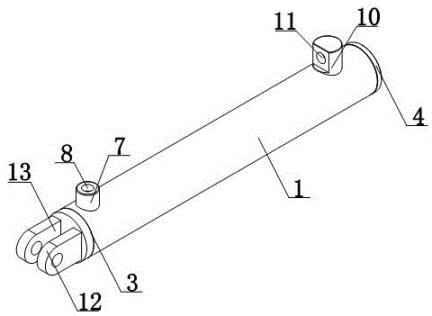
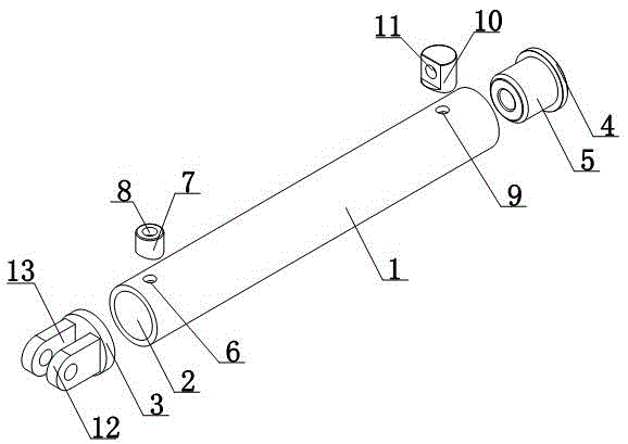
[0015] Such as figure 1 and figure 2 As shown, a cooling roll for printing paper transmission includes a cooling roll body 1, a cooling cavity 2 is provided at the axial position of the cooling roll body 1, a first end cover 3 is provided at one end of the cooling roll body 1, and the cooling The other end of the roller body 1 is provided with a second end cover 4, and the inward facing surface of the second end cover 4 is provided with an intubation tube 5, and the intubation tube 5 is inserted into the cooling cavity 2 of the cooling roll body 1; the cooling roll One end side wall of the roller body 1 is provided with an oil inlet 6, the oil ...


PUM


Abstract

The invention discloses a cooling roller for the transmission of printing paper. The cooling roller comprises a cooling roller body. A cooling cavity is formed in the axial position of the cooling roller body. A first end cover is arranged at one end of the cooling roller body. A second end cover is arranged at the other end of the cooling roller body. An insertion pipe is arranged on the inner side of the second end cover, and is inserted in the cooling cavity of the cooling roller body. An oil inlet is formed in one side wall at one end of the cooling roller body. An oil inlet pipe is arranged in the oil inlet. An oil feeding trough is formed in the oil inlet pipe axially, and is communicated with the cooling cavity. An oil outlet is formed in one side wall at the other end of the cooling roller body. An oil outlet column is arranged in the oil outlet. An oil discharging trough is formed in the oil outlet column, and is communicated with the cooling cavity. The temperature of the cooling roller body can be kept to be constant so as to achieve the cooling purpose, and the cooling roller plays a role in cooling during the transmission process of the printing paper conveniently.

Description

technical field [0001] The invention relates to a cooling roller, in particular to a cooling roller for printing paper transmission. Background technique [0002] The roller that is fed with cooling water is called a cooling roller. When the calendered film or adhesive tape is coated, in order to reduce the deformation caused by the shrinkage of the hot material when the finished product is rolled, the material is passed through a cooling roller to cool down the temperature before the roll is formed to reduce the deformation of the material. The cooling roller is the roller behind the web drying device, which is used to reduce the temperature of the web to the curing temperature of the thermosetting ink. The existing cooling roller is inconvenient to play a cooling role in the process of printing transmission, and the cooling effect is poor. Contents of the invention [0003] The present invention mainly solves the technical problems existing in the prior art, so as to p...

Claims


Application Information

Patent Timeline
IPC IPC(8): B41F23/04
CPCB41F23/0479
Inventor 胡和萍
Owner 胡和萍
Learn More