IGBT device testing device and method

A technology of testing device and testing method, which is applied in the field of power electronics, can solve problems such as the inability to understand the degradation process of failed devices and the changing rules of other parameters, and achieve the effect of improving the high-temperature and high-humidity withstand voltage reliability of IGBT

Active Publication Date: 2020-10-09
GLOBAL ENERGY INTERCONNECTION RES INST CO LTD +2
View PDF10 Cites 8 Cited by
  • Summary
  • Abstract
  • Description
  • Claims
  • Application Information

AI Technical Summary

Problems solved by technology

[0003] Therefore, the technical problem to be solved by the present invention is to overcome the defects in the prior art that cannot understand the degradation process of failed devices and other parameter variation rules under high temperature and high humidity conditions , thereby providing an IGBT device testing device and testing method

Method used


Image

  • IGBT device testing device and method
  • IGBT device testing device and method
  • IGBT device testing device and method

Examples


Embodiment 1

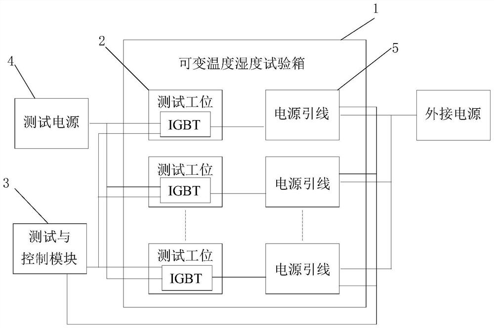
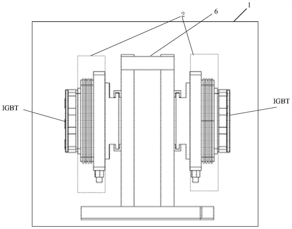
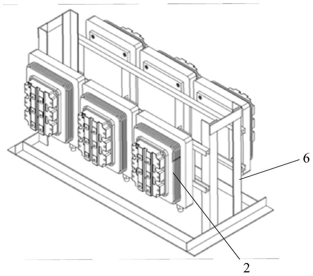
[0041] The embodiment of the present invention provides an IGBT device testing device, which is applied to occasions where it is necessary to analyze the degradation characteristics of the IGBT under high temperature, high humidity and high pressure blocking, such as figure 1 As shown, it includes: a variable temperature and humidity test chamber 1, a plurality of test stations 2, a test and control module 3, a test power source 4 and a plurality of power lead wires 5.

[0042] Since the high-temperature, high-humidity and high-voltage resistance tests of the IGBT are two independent tests in the prior art, and because it is impossible to test the degradation characteristic process and other parameter change rules of the IGBT under high-temperature, high-humidity, and high-voltage blocking, this paper In the embodiment of the invention, a variable temperature and humidity test chamber is used to control the temperature and humidity of the test environment, and all test stations...

Embodiment 2

[0060] An embodiment of the present invention provides a method for testing an IGBT device. The IGBT device is tested based on the IGBT device testing device in Embodiment 1, such as Figure 10 As shown, the IGBT device test methods include:

[0061] Step S11: Acquiring preset test temperature and preset test relative humidity.

[0062] Step S12: After controlling the temperature and humidity in the variable temperature and humidity test chamber to reach the preset test temperature and preset test relative humidity, the IGBT is periodically tested.

[0063] Step S13: After the periodic test of each IGBT is completed, record the number of periodic tests of each IGBT, and judge whether the number of periodic tests of each IGBT reaches the preset number of tests. When the number of periodic tests of the IGBT does not reach the preset number of tests, Return to the step of periodically testing the IGBT until the number of periodic tests of the IGBT reaches the preset number of te...


PUM


Abstract

The invention discloses an IGBT device testing device and testing method. The device comprises: a variable temperature and humidity test box, which is used for controlling the temperature and humidityof a test environment, wherein each test station is arranged in the variable temperature and humidity test box, and each test station is used for fixing one IGBT and dissipating heat of the IGBT; a test and control module, which is used for carrying out a period test on the IGBT and carrying out a high-voltage test and a static parameter test on the IGBT in sequence in each period test; a test power supply, which is connected with the grid electrode of the IGBT and used for outputting a test pulse signal, which is used for controlling the on-off state of the IGBT; and a plurality of power supply leads, which are used for connecting an external power supply with the IGBT and acquiring the leakage current of the IGBT. According to the invention, the variable temperature and humidity test box is used for keeping the test temperature in a high-temperature and high-humidity environment state, and after the IGBT is subjected to high-voltage test, the measurement power supply is used for carrying out static parameter test on the IGBT, so that the problem that the degradation process of a failure device and other parameter change rules cannot be understood is solved.

Description

technical field [0001] The invention relates to the technical field of power electronics, in particular to an IGBT device testing device and a testing method. Background technique [0002] With the rapid development of IGBT technology in recent years and the gradual increase of voltage and current levels, its application in power systems is becoming more and more extensive. However, the application environment of power systems is complex, and some use environments have high temperature and humidity and need to withstand High voltage, so some special requirements are put forward for IGBT devices: voltage withstand capability under high temperature and high humidity. The IEC60747-9 standard requires the high temperature reverse bias (HTRB) test, which is one of the must-test items for the reliability of IGBT devices. The standard stipulates that the IGBT needs to withstand 80% of the rated voltage for 1000 hours at the highest operating junction temperature; while JESD22- The...

Claims


Application Information

Patent Timeline
Patent Type & Authority Applications(China)
IPC IPC(8): G01R31/26G01R31/52
CPCG01R31/2642G01R31/2608G01R31/52
Inventor 李尧圣李金元张雷刘朝章燕树民苏冰
Owner GLOBAL ENERGY INTERCONNECTION RES INST CO LTD
Why Eureka
Try Eureka