Valve element injection mold

A technology of injection molds and valve cores, which is applied to household appliances, other household appliances, household components, etc., and can solve problems such as slow production speed, poor quality, and low precision

Active Publication Date: 2016-12-07
宁波玛仕电磁科技有限公司
View PDF4 Cites 8 Cited by
  • Summary
  • Abstract
  • Description
  • Claims
  • Application Information

AI Technical Summary

Problems solved by technology

[0002] The spool is a valve part that uses its movement to realize the basic functions of direction control, pressure control or flow control. There are many types of existing spools, mainly divided into plastic spools, copper spools, cast iron spools, etc., among which , the plastic spool is widely used due to its stable performance, low cost, and according to the existing technology, the plastic spool is generally formed by molding, which has high cost, low precision, and slow production speed, which is not conducive to mass production and poor quality.

Method used


Image

  • Valve element injection mold
  • Valve element injection mold
  • Valve element injection mold

Examples


Embodiment Construction

[0024] The present invention will be further described below in conjunction with the accompanying drawings and specific embodiments.

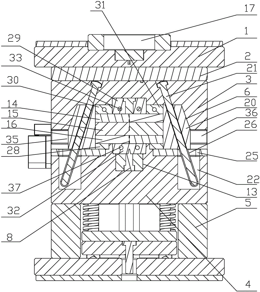
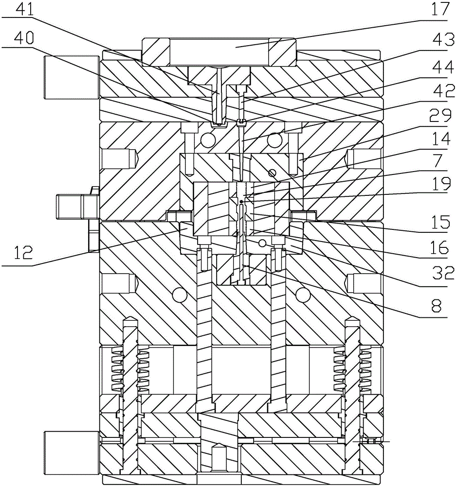
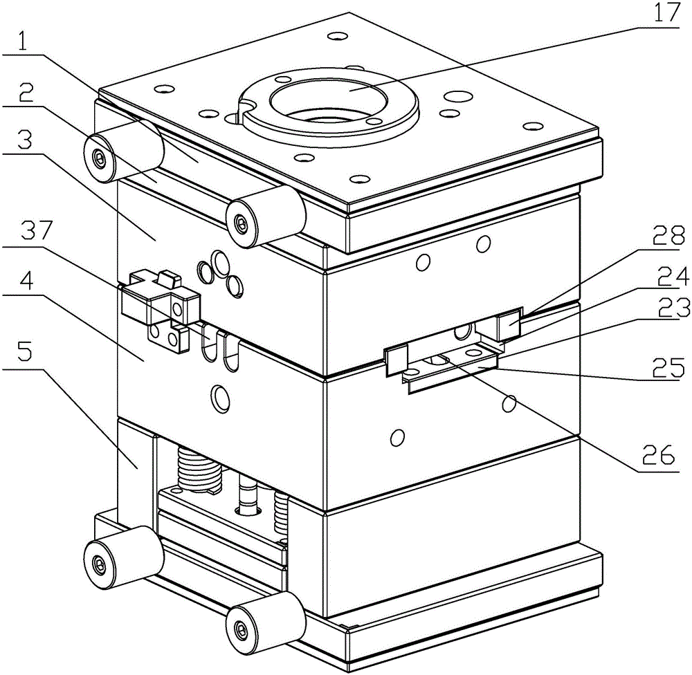
[0025] As shown in the figure, the present invention provides a valve core injection mold, including a cover plate 1, an upper mold fixing plate 2, an upper mold plate 3, a lower mold plate 4, a mold foot 5, a sprue 17 fixed on the cover plate 1 and a valve Core 7, runners are provided under the gate 17, the upper mold fixing plate 2 is fixed on the lower surface of the cover plate 1, the lower mold plate 4 is fixed on the upper surface of the mold foot 5, and the The upper mold plate 3 is located between the upper mold fixed plate 2 and the lower mold plate 4, and the outer surface of the valve core 7 is provided with a first protrusion 9, a second protrusion 10 and a second protrusion along the axial direction of the valve core 7 from top to bottom. Three protrusions 11, the outer surfaces of the first protrusion 9, the second protrusion 10 a...


PUM


Abstract

The invention discloses a valve element injection mold. The valve element injection mold comprises a cover plate (1), an upper mold fixing plate (2), an upper mold plate (3), a lower mold plate (4), a mold leg (5), a spout (17) fixed to the cover plate (1), and a valve element (7), wherein a runner is arranged below the spout (17); the upper mold fixing plate (2) is fixed to the lower surface of the cover plate (1); the lower mold plate (4) is fixed to the upper surface of the mold leg (5); the upper mold plate (3) is located between the upper mold fixing plate (2) and the lower mold plate (4); a first protrusion (9), a second protrusion (10) and a third protrusion (11) are arranged on the outer side face of the valve element (7) in the axis direction of the valve element (7) in sequence from top to bottom; and annular grooves are formed in the outer side faces of the first protrusion (9), the second protrusion (10) and the third protrusion (11). The valve element injection mold is low in cost, high in precision, high in production speed, capable of achieving batch production and good in quality.

Description

technical field [0001] The invention relates to the field of injection molds, in particular to a valve core injection mold. Background technique [0002] The spool is a valve part that uses its movement to realize the basic functions of direction control, pressure control or flow control. There are many types of existing spools, mainly divided into plastic spools, copper spools, cast iron spools, etc., among which , Plastic spools are widely used due to their stable performance, low cost, and according to the prior art, plastic spools are generally formed by compression molding, which has high cost, low precision, and slow production speed, which is not conducive to mass production and poor quality. Contents of the invention [0003] The technical problem to be solved by the present invention is to overcome the above defects of the prior art and provide a valve core injection mold with low cost, high precision, fast production speed, mass production and good quality. [0...

Claims


Application Information

Patent Timeline
Patent Type & Authority Applications(China)
IPC IPC(8): B29C45/26B29C45/33B29L31/00
CPCB29C45/2602B29C45/33B29L2031/7506
Inventor 徐华生
Owner 宁波玛仕电磁科技有限公司
Why Eureka
Try Eureka