
Discharging device for paper tube detection

A discharge device and paper tube technology, applied in the direction of transportation and packaging, conveyor objects, etc., can solve the problems of low discharge efficiency and low production efficiency, achieve high discharge effect, reduce work intensity, and improve detection efficiency Effect

Active Publication Date: 2016-06-08
浙江三信智能机械股份有限公司
View PDF7 Cites 1 Cited by
  • Summary
  • Abstract
  • Description
  • Claims
  • Application Information

AI Technical Summary

Problems solved by technology

[0003] The technical problem to be solved by the present invention is to provide a paper tube detection and discharge device, which can effectively solve the problems of low discharge efficiency and low production efficiency after the existing paper tube detection

Method used


Image

  • Discharging device for paper tube detection
  • Discharging device for paper tube detection
  • Discharging device for paper tube detection

Examples


Embodiment Construction

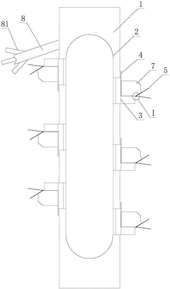
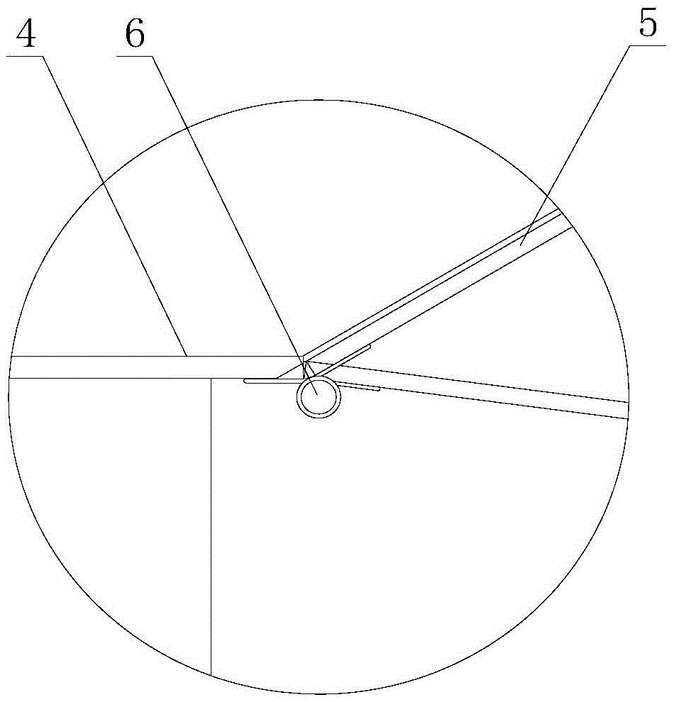
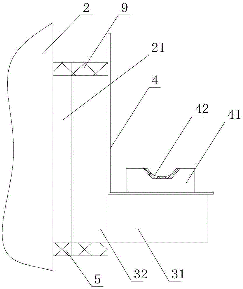
[0015] Such as figure 1 , figure 2 , image 3 As shown, a paper tube detection and discharging device includes a frame 1, a transmission chain 2, a bottom plate 3, a discharge hopper 4 and a flap 5, the transmission chain 2 is arranged on the frame 1, and the bottom plate 3 is fixedly connected to the transmission chain 2 On the top, the discharge hopper 4 is fixedly connected to the bottom plate 3, and the turnover plate 5 is arranged on the discharge hopper 4 inclined upwards, and a torsion spring 6 is arranged between the turnover plate 5 and the discharge hopper 4 to control the downward fall and return of the turnover plate 5 , one end of the torsion spring 6 is fixedly connected to the turnover plate 5, the other end of the torsion spring 6 is fixedly connected to the discharge hopper 4, the discharge hopper 4 is provided with a limiting baffle 7, and the limit baffle 7 is connected to the turnover plate 5, The bottom plate 3 includes a horizontal part 31 and a vertic...


PUM


Abstract

The invention relates to a discharging device for paper tube detection. The discharging device comprises a rack, a transmission chain, bottom plates, discharging hoppers and turnover plates. The bottom plates are fixedly connected to the transmission chain. The turnover plates are arranged on the discharging hoppers in an upwards inclined manner. A torsion spring is arranged between each turnover plate and the corresponding discharging hopper and used for controlling the corresponding turnover plate to turn over downwards and return. A limiting baffle is arranged on each discharging hopper. The discharging device has the beneficial effects that paper tubes are discharged and collected through the discharging hoppers, then transmission discharging of the discharging hoppers is achieved through the transmission chain, the work intensity in the existing paper tube detection discharging process is reduced, the detection efficiency is improved, and the discharging effect is good; by means of the arrangement of the turnover plates, the paper tubes can be prevented from falling off in the ascending process of the discharging hoppers; by means of the arrangement of the torsion springs, it is guaranteed that the paper tubes can enter the discharging hoppers normally, and return of the turnover plates is guaranteed; and by means of the limiting baffles, the return amount of the turnover plates can be effectively limited, and it is guaranteed that the turnover plates return reliably.

Description

technical field [0001] The invention relates to a paper tube detecting and discharging device. Background technique [0002] At present, paper tubes need to be inspected after production. Most of the existing transmission mechanisms adopt gear transmission or belt transmission. After the transmission inspection, the paper tubes are all manually operated when they are discharged and collected, and two or three operators are required. Personnel collect the qualified, unqualified and re-tested respectively. The collection workload is heavy and the output efficiency is low, which affects production efficiency. Contents of the invention [0003] The technical problem to be solved by the present invention is to provide a paper tube detection and discharge device, which can effectively solve the problems of low discharge efficiency and low production efficiency after the existing paper tube detection. [0004] In order to solve the above technical problems, the present invention...

Claims


Application Information

Patent Timeline
IPC IPC(8): B65G47/40
CPCB65G47/40
Inventor 严滔滔
Owner 浙江三信智能机械股份有限公司
Learn More