Mechanical equipment lifting frame and lifting method

A technology of mechanical equipment and hoisting frame, applied in hoisting devices, portable lifting devices, etc., can solve problems such as time-consuming, laborious, dangerous, and difficult to move and hoist large equipment, and achieve convenient use, small space occupation, and convenient movement and hoisting Effect

Active Publication Date: 2016-06-08
PETROCHINA CO LTD
View PDF5 Cites 10 Cited by
  • Summary
  • Abstract
  • Description
  • Claims
  • Application Information

AI Technical Summary

Problems solved by technology

[0003] However, due to many reasons such as the early construction of the factory area and the space limitation in the later stage, the existing hoisting equipment such as cranes and forklifts cannot meet the existing conditions of use. As a result, hoisting equipment such as mobile cranes and forklifts cannot enter, especially the movement and hoisting of large-scale motors and pumps above 800KW is more difficult, not only time-consuming and labor-intensive, but also extremely dangerous

Method used


Image

  • Mechanical equipment lifting frame and lifting method
  • Mechanical equipment lifting frame and lifting method
  • Mechanical equipment lifting frame and lifting method

Examples


Embodiment 1

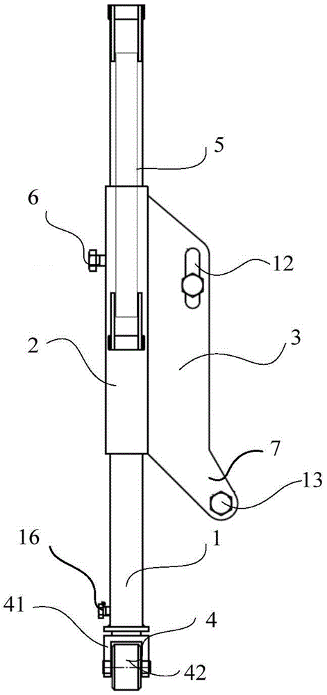
[0036] figure 1 It is the front view of the mechanical equipment lifting frame of the first embodiment of the present invention; please refer to figure 1 , the present embodiment provides a mechanical equipment hoisting frame, including a column 1, a sliding sleeve 2 is set on the column 1, and a connecting piece 3 for connecting with the mechanical equipment to be hoisted is fixedly arranged on the sliding sleeve 2; the bottom end of the column 1 A roller device 4 is provided; a driving device 5 for driving the sliding sleeve 2 to move axially relative to the column 1 is provided between the sliding sleeve 2 and the column 1 ; a locking device 6 for locking the sliding sleeve 2 is also provided on the sliding sleeve 2 .

[0037] Specifically, the shape of the connecting piece 3 can be plate-shaped or other shapes, and the plate-shaped connecting piece 3 can save costs and ensure the convenience of connecting the connecting piece 3 and the mechanical equipment to be hoisted; i...

Embodiment 2

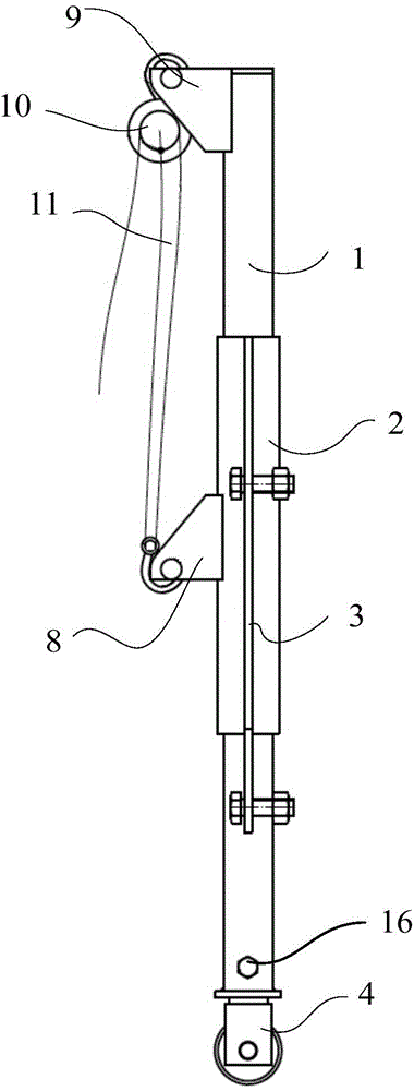
[0045] figure 2 It is the left view of the mechanical equipment lifting frame of the second embodiment of the present invention; this embodiment is based on the first embodiment, and the driving device adopts the chain-reversing device as an example to describe in detail. Such as figure 2 As shown, in this embodiment, the driving device is a chain-rewinding device; the sliding sleeve 2 is fixed with a first lifting lug 8, the top of the column 1 is provided with a second lifting lug 9, and the chain-rewinding device is installed on the second lifting lug 9 and the first lug 8. Specifically, in order to better control the chain-winding device, the first lifting lug 8 and the connecting piece 3 can be arranged on different busbars of the sliding sleeve 2. Of course, the first lifting lug 8 and the connecting piece 3 can also be set on the same busbar. In addition, even the first lifting lug 8 can be directly arranged on the connecting piece 3. At the same time, in order to e...

Embodiment 3

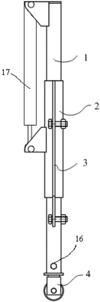
[0050] Such as image 3 It is the left view of the mechanical equipment in the second embodiment of the present invention. This embodiment is based on the first embodiment, and the driving device adopts a hydraulic cylinder as an example to describe in detail. Such as image 3 As shown, in this embodiment, the driving device can be a hydraulic cylinder 17, the cylinder body of the hydraulic cylinder 17 is hinged to the top of the column 1, and the piston rod of the hydraulic cylinder 17 is fixedly connected to the sliding sleeve 2. The hydraulic cylinder 17 is driven by hydraulic pressure to change the hydraulic energy into mechanical energy, and the extension and contraction of the piston rod pushes and pulls the sliding sleeve 2 to slide up and down in the axial direction; of course, in addition to the form of the hydraulic cylinder, you can also choose a similar device such as an air cylinder. I won't go into details here. The use of hydraulic cylinders can realize automa...


PUM


Abstract

The invention provides a mechanical equipment lifting frame and a lifting method. The mechanical equipment lifting frame comprises a stand column; a slide sleeve sleeves the stand column; the slide sleeve is fixedly provided with a connecting piece for connecting with mechanical equipment to be lifted; a roller device is arranged at the bottom end of the stand column; a driving device for driving the slide sleeve to axially move relative to the stand column is arranged between the slide sleeve and the stand column; and the slide sleeve is provided with a locking device for locking the slide sleeve. The mechanical equipment lifting frame, provided by the invention, is smaller in size, can adapt to narrow factory building space, is simple and flexible in operation, and can conveniently and quickly shift and lift the mechanical equipment.

Description

technical field [0001] The invention relates to hoisting equipment technology, in particular to a mechanical equipment hoisting frame and a hoisting method. Background technique [0002] In production, it is often necessary to move mechanical equipment such as motors and pumps from one place to another. At present, cranes and forklifts are often used for lifting and moving large-scale equipment. [0003] However, due to many reasons such as the early construction of the factory area and the space limitation in the later stage, the existing hoisting equipment such as cranes and forklifts cannot meet the existing conditions of use. As a result, hoisting equipment such as mobile cranes and forklifts cannot enter, especially the movement and hoisting of large-scale equipment such as large motors and pumps above 800KW is more difficult, not only time-consuming and laborious, but also extremely dangerous. Contents of the invention [0004] In view of the above-mentioned defects...

Claims


Application Information

Patent Timeline
Patent Type & Authority Applications(China)
IPC IPC(8): B66D3/00
Inventor 柳楠宋中华毛仲强阳广龙丛蕾胡启良张北王俊奇赵振兴谭川江
Owner PETROCHINA CO LTD
Why Eureka
Try Eureka