Heat exchange pipe

A technology of heat exchange tubes and draft tubes, applied in heat exchange equipment, tubular elements, heat transfer modification, etc., which can solve the adverse effects of heat exchange tubes 9 on heat exchange effects, poor heat exchange effects of heat exchange tubes 9, complex structure, etc.

Inactive Publication Date: 2016-06-08
SUNONWEALTH ELECTRIC MACHINE IND
View PDF6 Cites 0 Cited by
  • Summary
  • Abstract
  • Description
  • Claims
  • Application Information

AI Technical Summary

Problems solved by technology

[0003] However, because the above-mentioned existing heat exchange tube 9 must use two hollow guide tubes such as the outer cylinder body 91 and the heat conduction inner tube 92, and two fin groups (i.e. the heat conduction ring 94 and the heat dissipation fins) must be used together. 96) to form a heat exchange tube structure with two flow passages (that is, the annular cooling chamber 93 and the inner cooling body 95) respectively having fin groups. Therefore, there are problems such as numerous components, inconvenient assembly, and relatively high manufacturing costs.
[0004] Furthermore, the heat conduction ring body 94 and the cooling fins 96 of the existing heat exchange tube 9 simply provide a heat conduction path. The ratio of the heat conduction ring 94 and the cooling fins 96 is low, which will lead to poor heat exchange effect of the existing heat exchange tube 9
[0005] In add

Method used


Image

  • Heat exchange pipe
  • Heat exchange pipe
  • Heat exchange pipe

Examples


Embodiment Construction

[0068] In order to make the above and other objects, features and advantages of the present invention more comprehensible, preferred embodiments of the present invention will be described in detail below together with the accompanying drawings.

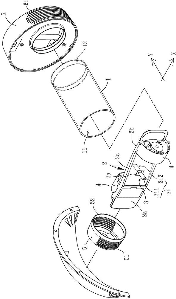
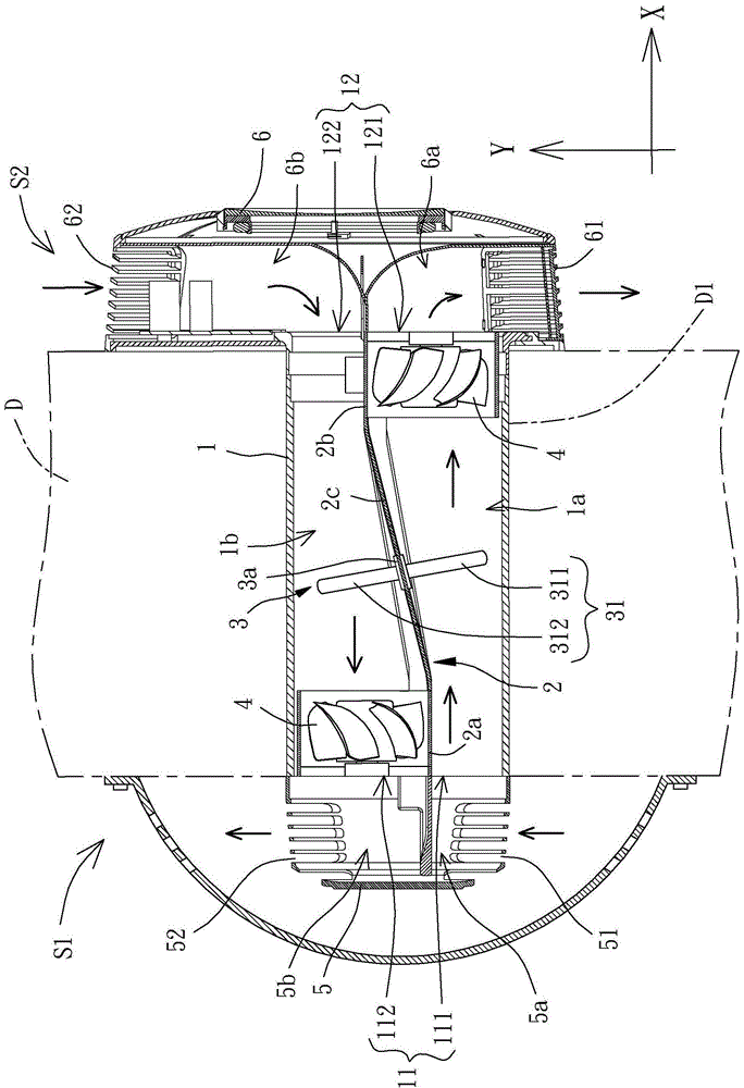
[0069] Please refer to figure 2 and image 3 As shown, the heat exchange tube in the first embodiment of the present invention is used to install on a spacer D, one side of the spacer D is an external space S1, and the opposite side of the spacer D is an inner space S1. Space S2. Wherein, the heat exchange tube includes a flow guide tube 1 , a separator 2 and at least one heat conducting member 3 . The duct 1 is installed in a through hole D1 of the spacer D, the spacer 2 is disposed inside the duct 1 , and the at least one heat conducting element 3 passes through the spacer 2 .

[0070] Under the premise of having the function of allowing various fluids (gas or liquid) to circulate, the guide tube 1 can use various hollow cylinde...


PUM


Abstract

A heat exchange pipe is disclosed for improving heat exchanging effect. The heat exchange pipe includes a conduction pipe, a separation member and at least one heat conducting member. The conduction pipe has a first end and a second end opposite to the first end. The first end has a first opening and a second opening, and the second end has a third opening and a forth opening. The separation member is mounted inside the conduction pipe and separates a first flow passage and a second flow passage of conduction pipe. The first flow passage communicates with the first opening and the third opening. The second flow passage communicates with the second opening and the forth opening. The heat conducting member has a pillar with a first section and a second section connected to each other. The pillar penetrates through the separation member, and the first and second sections located in the first and second flow passages respectively.

Description

technical field [0001] The invention relates to a heat exchange tube, especially a heat exchange tube which can be used for fluid circulation. Background technique [0002] Please refer to figure 1 As shown, it is an existing heat exchange tube 9, which generally has an outer cylinder 91 and a heat-conducting inner tube 92, and the heat-conducting inner tube 92 is arranged inside the outer cylinder 91; wherein, An annular cooling chamber 93 is formed between the outer cylinder 91 and the heat-conducting inner pipe 92, and a heat-conducting ring 94 with continuous wavy fins is installed in the annular cooling chamber 93; An inner radiating body 95, the inner radiating body 95 is provided with several radiating fins 96; thereby, when the high-temperature fluid passes through the inside of the heat exchange tube 9, the fins of the heat-conducting ring 94 can absorb heat to the high-temperature fluid, and Furthermore, the heat can be dissipated and conducted to the inner radia...

Claims


Application Information

Patent Timeline
IPC IPC(8): F28F1/42F28F13/12
Inventor 洪银树李明聪蔡期琮
Owner SUNONWEALTH ELECTRIC MACHINE IND
Why Eureka
Try Eureka