
Gain-and-direction-orientated structure thermal deformation compensation method for satellite-borne active phase control array antenna

A phased array antenna, deformation compensation technology, applied in the direction of the antenna, electrical components, etc., can solve the problems of thermal deformation of the structure, deterioration of the electrical performance of the antenna, etc.

Active Publication Date: 2016-07-06
XIDIAN UNIV
View PDF4 Cites 17 Cited by
  • Summary
  • Abstract
  • Description
  • Claims
  • Application Information

AI Technical Summary

Problems solved by technology

[0007] In view of the above problems, the present invention is based on the electromechanical coupling model of the spaceborne active phased array antenna, combined with the phase adjustment method, realizes the electrical performance compensation of the deformed spaceborne active phased array antenna, which can be used to solve the problems caused by environmental thermal load and device The deterioration of the electrical performance of the antenna caused by the thermal deformation of the structure caused by thermal power consumption, so as to ensure that the antenna can work normally in the service environment

Method used


Image

  • Gain-and-direction-orientated structure thermal deformation compensation method for satellite-borne active phase control array antenna
  • Gain-and-direction-orientated structure thermal deformation compensation method for satellite-borne active phase control array antenna
  • Gain-and-direction-orientated structure thermal deformation compensation method for satellite-borne active phase control array antenna

Examples


Embodiment Construction

[0065] Below in conjunction with accompanying drawing and embodiment the present invention will be further described

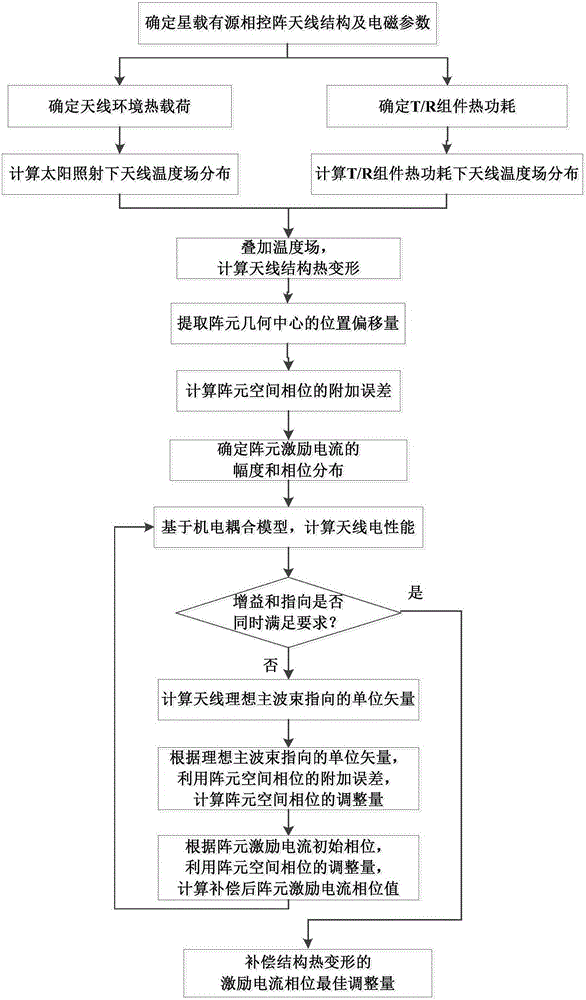
[0066] refer to figure 1 , the present invention is a method for compensating thermal deformation of a space-borne active phased array antenna structure oriented to gain and direction, and the specific steps are as follows:

[0067] Step 1. Determine the structural parameters, material properties and electromagnetic parameters of the spaceborne active phased array antenna.

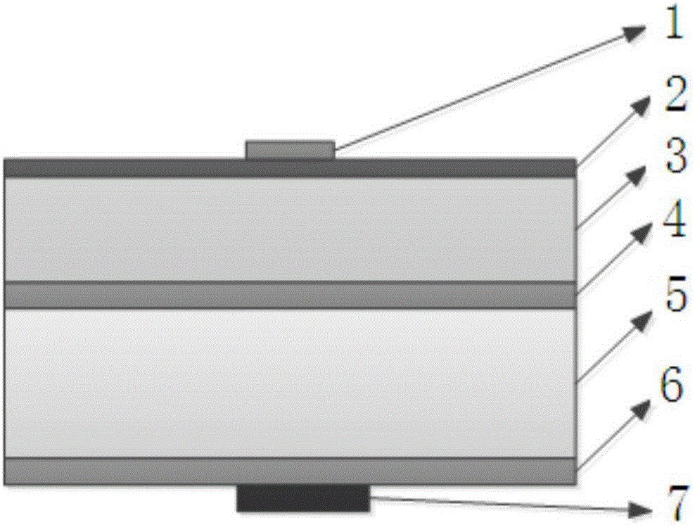
[0068] Such as figure 2 As shown, the structural parameters of the spaceborne active phased array antenna include the number of rows M, the number of columns N and the spacing d between the elements in the antenna x and d y , geometric parameters of printed board 2, paper honeycomb 3, aluminum honeycomb upper panel 4, aluminum honeycomb 5, aluminum honeycomb lower panel 6 and T / R components; microstrip patch antenna 1 folded on printed board 2, heat source 7 It is arranged under the a...


PUM


Abstract

The invention discloses a gain-and-direction-orientated structure thermal deformation compensation method for a satellite-borne active phase control array antenna. The method comprises the steps of determining structural parameters, material attributes and electromagnetic parameters of the antenna; determining antenna environment thermal load; calculating antenna temperature field distribution under sunshine; determining T / R assembly thermal power consumption; calculating antenna temperature field distribution under the T / R assembly thermal power consumption; performing temperature field superposition and calculating the thermal deformation of the antenna structure; extracting position offset in the array element geometric center; calculating the additional error of the array element space phase; determining the amplitude and phase distribution of array element excitation current; calculating the electrical performance of the antenna; judging whether gain and direction are both satisfied simultaneously or not; and calculating the antenna ideal main beam directed unit vector, the adjusting amount of the array element space phase, and the phase current of the compensated array element excitation current. The compensation method provided by the invention is combined with a phase adjusting method, so that the electrical performance compensation to the deformed satellite-borne active phase control array antenna is realized; the problem of antenna electrical performance degradation caused by structural thermal deformation is solved; and the normal operation of the antenna can be ensured.

Description

technical field [0001] The invention belongs to the technical field of antennas, and in particular relates to a method for compensating thermal deformation of a space-borne active phased array antenna structure oriented to gain and direction. Background technique [0002] With the rapid development of space-borne antennas, the performance requirements for multi-function, multi-band, long-distance, and high-power antennas are getting higher and higher. Due to the increasing demand for satellite communication data transmission capacity, the original small-aperture low-gain antenna can no longer meet the application requirements. The use of space-borne active phased array antennas is one of the ways to solve the above problems. It serves as the "eyes" and "ears" of satellite systems such as space communication, electronic reconnaissance, navigation, and environmental monitoring. Independent control of multiple spot beams not only overcomes the problems of large inertia, slow s...

Claims


Application Information

Patent Timeline
IPC IPC(8): H01Q3/34
CPCH01Q3/34
Inventor 王从思程景胜王艳毛静钟剑锋李斌王璐黄进梁震涛彭雪林庞毅王志海
Owner XIDIAN UNIV
Learn More