Motor rotor displacement measurement method

A displacement measurement and motor stator technology, which is applied in the field of long-stroke subdivision measurement algorithms, can solve the problems of circuit complexity, low noise, and difficult industrial real-time application, and achieves reduced structural complexity and high-precision mover displacement measurement. , the effect of cost reduction

Active Publication Date: 2012-07-18
TSINGHUA UNIV +1
View PDF6 Cites 18 Cited by
  • Summary
  • Abstract
  • Description
  • Claims
  • Application Information

AI Technical Summary

Problems solved by technology

Similar to the patent ZL201010034274.4, complex nonlinear equations need to be solved, which brings difficulties to industrial real-time applications; the measurement results of other similar patent description methods require a high signal-to-noise ratio for the measurement signal itself, which poses a challenge to the implementation circuit. Noise and other high requirements

Method used


Image

  • Motor rotor displacement measurement method
  • Motor rotor displacement measurement method
  • Motor rotor displacement measurement method

Examples


Embodiment

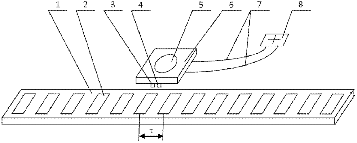
[0041] refer to figure 1 , 3, demonstrating the displacement measurement process of the mover 6, so as to better understand the present invention.

[0042] The pole distance of the magnetic field is τ=35.35mm, and the distance between the sine sensor and the cosine sensor is τ / 4, that is, 8.8375mm. Using 12-bit AD sampling, the noise level Calculate n=8 according to the calculation formula of the maximum number of multiplication operations.

[0043] 1) According to the above calculation, in the sinusoidal magnetic field formed by the stator magnetic steel array 2 of the moving coil linear motor, two magnetic induction sensors are arranged on the mover along the moving direction of the mover: the sine sensor 3 and the cosine sensor 4, the τ It is the magnetic field pole distance of the sinusoidal magnetic field of the motor, and the distance between the sine sensor 3 and the cosine sensor 4 is τ / 4, which is 8.8375 mm. Get the sinusoidal measurement signal S 0 , the samplin...


PUM


Abstract

The invention discloses a motor rotor displacement measurement method. The method comprises the following steps of: arranging two magnetic induction intensity sensors on a rotor along a moving direction of the rotor, wherein a distance between the two sensors is 1/4 of a polar distance of a magnetic field; quantizing sampled signals of the two sensors through a signal processing circuit and performing n frequency multiplication operation after amplitude normalization; and performing zero-crossing point detection, generating a group of orthogonal pulse signals, and detecting the number of pulses of the pulse signals and phase difference of the group of orthogonal pulse signals. The polar distance tau of the magnetic field is subdivided to tau/2 so as to realize high-precision motor rotor displacement measurement according to sinusoidal magnetic field information of a magnetic steel array of the motor rotor in the moving direction of the rotor directly. By the method, the problems that a calculation method is complex, hardware is inconvenient to mount and a measurement device is high in cost due to the high-precision requirement of the motor rotor displacement measurement can be solved.

Description

technical field [0001] The invention relates to a method for measuring the displacement of a mover in a motor with a sinusoidal magnetic field model, such as a moving-coil linear motor and a rotating motor, in particular to a long-stroke subdivision measurement algorithm. Background technique [0002] Precision dynamic measurement technology is an important link to realize dynamic precision control. In conventional application fields, sensors such as grating scales, laser interferometers, and magnetic scale scales are used as measurement methods for linear and angular displacements of moving coil linear motors and rotating motors. Patent 200720002447.8 describes the use of a grating position detection encoder for position detection, and patent 200610033455 describes the use of a grating encoder for real-time position feedback for positioning. These sensors need to arrange magnetic fields, grids and other devices that specially generate displacement signal characteristics on...

Claims


Application Information

Patent Timeline
Patent Type & Authority Applications(China)
IPC IPC(8): G01B7/02
Inventor 胡金春朱煜尹文生陈龙敏杨开明张鸣徐登峰穆海华胡楚雄刘召
Owner TSINGHUA UNIV
Why Eureka
Try Eureka