Method for removing moiré

A technology of Moore interference and cylindrical lens, applied in the field of optics, can solve problems such as the generation of cylindrical lens devices, affecting the display effect, affecting viewing comfort, etc., and achieve the effect of solving technical constraints

Active Publication Date: 2018-03-27
NINGBO VISION DISPLAY TECH
View PDF4 Cites 0 Cited by
  • Summary
  • Abstract
  • Description
  • Claims
  • Application Information

AI Technical Summary

Problems solved by technology

[0006] The purpose of the present invention is to solve the problem that the naked-eye 3D display uses a lenticular device to produce moiré patterns, thereby affecting the display effect and viewing comfort, and provides a method for eliminating moiré patterns

Method used


Image

  • Method for removing moiré
  • Method for removing moiré
  • Method for removing moiré

Examples


specific Embodiment approach 1

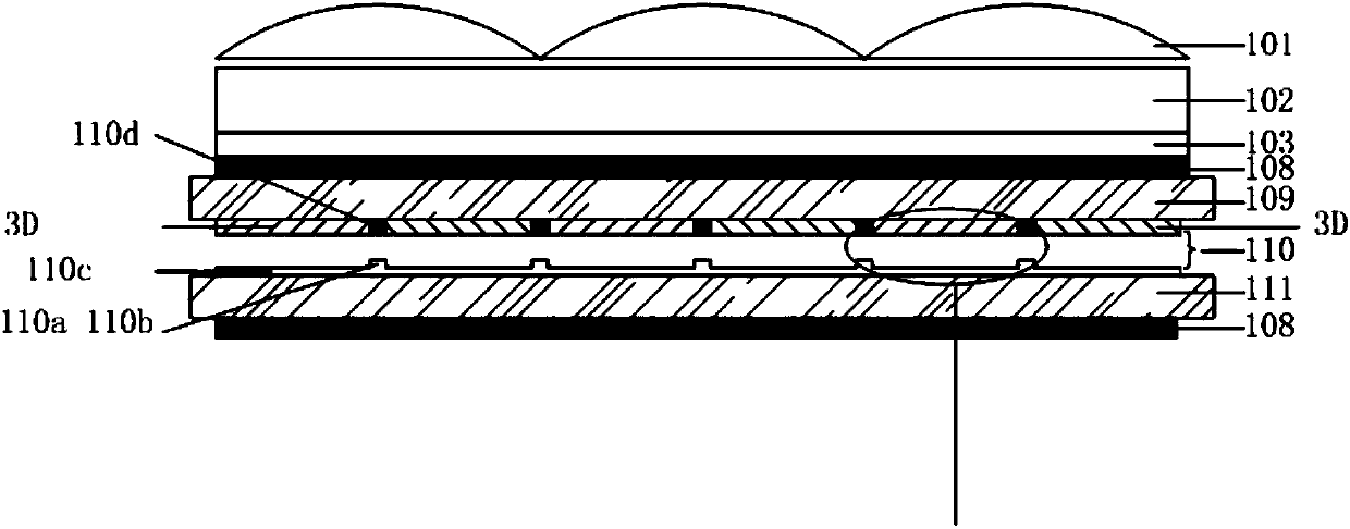
[0018] Specific implementation mode one: the following combination Figure 3 to Figure 6 Describe this embodiment mode, the method for eliminating moiré fringe described in this embodiment mode, the 3D display that this method is aimed at includes cylindrical lens grating 101, PET base material 102, OCA optical adhesive 103 and liquid crystal screen, and liquid crystal screen comprises color filter glass 109, TFT glass 111, the upper surface of color film glass 109 and the lower surface of TFT glass 111 are respectively provided with a polarizer 108. The color film glass 109 and TFT glass 111 are provided with a display screen core layer 110, and the display screen core layer 110 includes three Layer structure: upper glass, lower glass and liquid crystal with a thickness of only about 4 microns between them; The lower glass is provided with a circuit layer, which is made of conductive metal or metal oxide such as ITO or molybdenum-aluminum-molybdenum. The circuit layer include...

specific Embodiment approach 2

[0026] Specific implementation mode two: the following combination Figure 5 with Image 6 Describe this embodiment mode. This embodiment mode will further explain Embodiment 1. The cylindrical lens grating can adopt two structural modes:

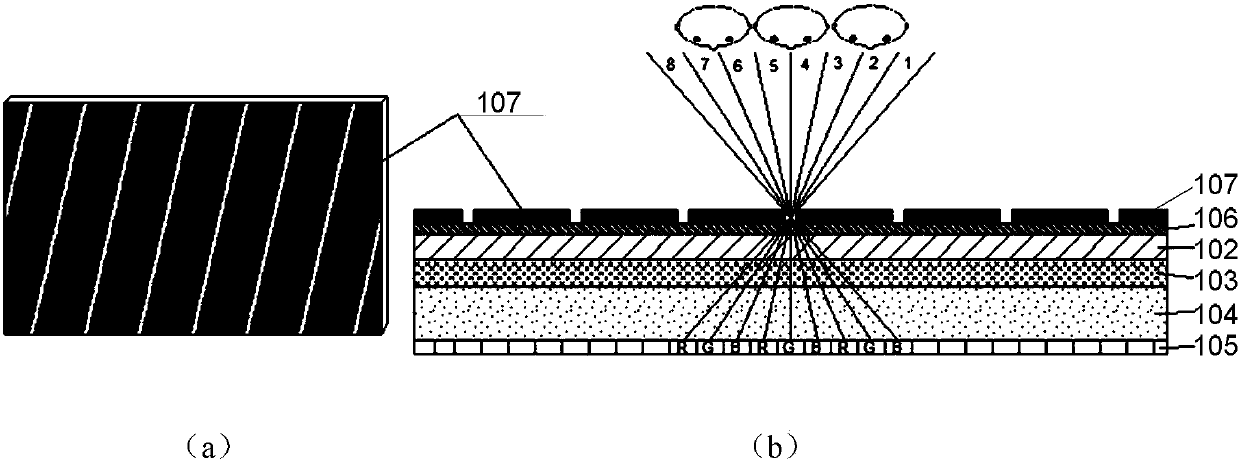
[0027] The first structure: such as Figure 5 As shown, the cylindrical lens adopts a single convex grating structure. n1 is the refractive index of the prism; n2 is the refractive index of the cylindrical lens embedded in the prism; and n2

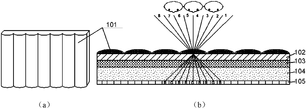
[0028] The second structure, such as Image 6 As shown, the cylindrical lens adopts a combined grating; the combined grating is composed of a concave grating with a refractive index of n2 and a convex grating with a refractive index of n3, and the combined grating is equivalent to an ordinary convex lens. n1 is the refractive index of the prism; n2

specific Embodiment approach 3

[0029] Embodiment 3: This embodiment further explains Embodiment 2. The height of the triangular prism does not exceed 1 / 3 of the height of the cylindrical lens embedded in it. If it exceeds this value, it is adjusted by increasing the thickness of the base of the cylindrical lens.


PUM


Abstract

The invention provides a method for eliminating Moore interference fringes, belongs to the optical field, and aims to solve the problem that the watching comfort level is influenced due to Moore fringes generated by a column lens device adopted by a naked eye 3D display. The method comprises the steps of: a triangular refraction area is embedded in each section of an optical grating, the extension direction of the triangular refraction area is identical with the extension direction of a single optical grating of a column lens, and the triangular refraction area are corresponding to black matrixes on a display screen in position; each triangular refraction area is of a triple prism structure whose cross section is in an isosceles triangle shape, the bottom surface of the triple prism is arranged on the bottom surface, facing the display, of the column lens device, and the width of the bottom edge of the isosceles triangle is larger than or equal to the width of the black matrix. The top angle of the isosceles triangle is shown in the specification, wherein n2 is smaller than n1. Light transmitted by the black matrixes is irradiated to the triangular refraction area and then total reflection happens, the beam of light is refracted to left and right sides and jumps out of views of people, and the comfort level of human eyes is not influenced.

Description

technical field [0001] The present invention belongs to the field of optics. Background technique [0002] Glasses-free 3D means that you can enjoy realistic images that are "ready to come out" without wearing any auxiliary equipment such as special glasses, making people feel like "being in a wonderland". [0003] In 2014, the sales volume of smart phones in my country was about 400 million units, and the market size exceeded 100 billion per year. Although the sales volume is increasing, the sales price is falling. The reason is that the current smart terminal products have no new selling points to attract In people's eyes, the popularity of 3D is considered by many manufacturers as a new growth point, but how to get rid of the shackles of glasses and make 3D applicable anytime and anywhere has become a must for many companies. Glasses-free 3D technology has rapidly entered the stage of industrialization and market application after years of accumulation. With the increasi...

Claims


Application Information

Patent Timeline
Patent Type & Authority Patents(China)
IPC IPC(8): G02B27/22
CPCG02B30/26G02B30/27
Inventor 顾开宇
Owner NINGBO VISION DISPLAY TECH
Why Eureka
Try Eureka