Method and system for implementing traceability based on monitoring points

An implementation method and technology for implementing a system, applied in the field of traceability implementation methods and systems based on monitoring points, can solve problems such as inconvenience, insufficient causal relationships, and complex artificial intelligence analysis and inference processes, and achieve strong monitoring and management capabilities and virtual reality. The effect of high degree and convenient traceability calculation

Active Publication Date: 2018-10-09
ADVANCED NEW TECH CO LTD
View PDF5 Cites 0 Cited by
  • Summary
  • Abstract
  • Description
  • Claims
  • Application Information

AI Technical Summary

Problems solved by technology

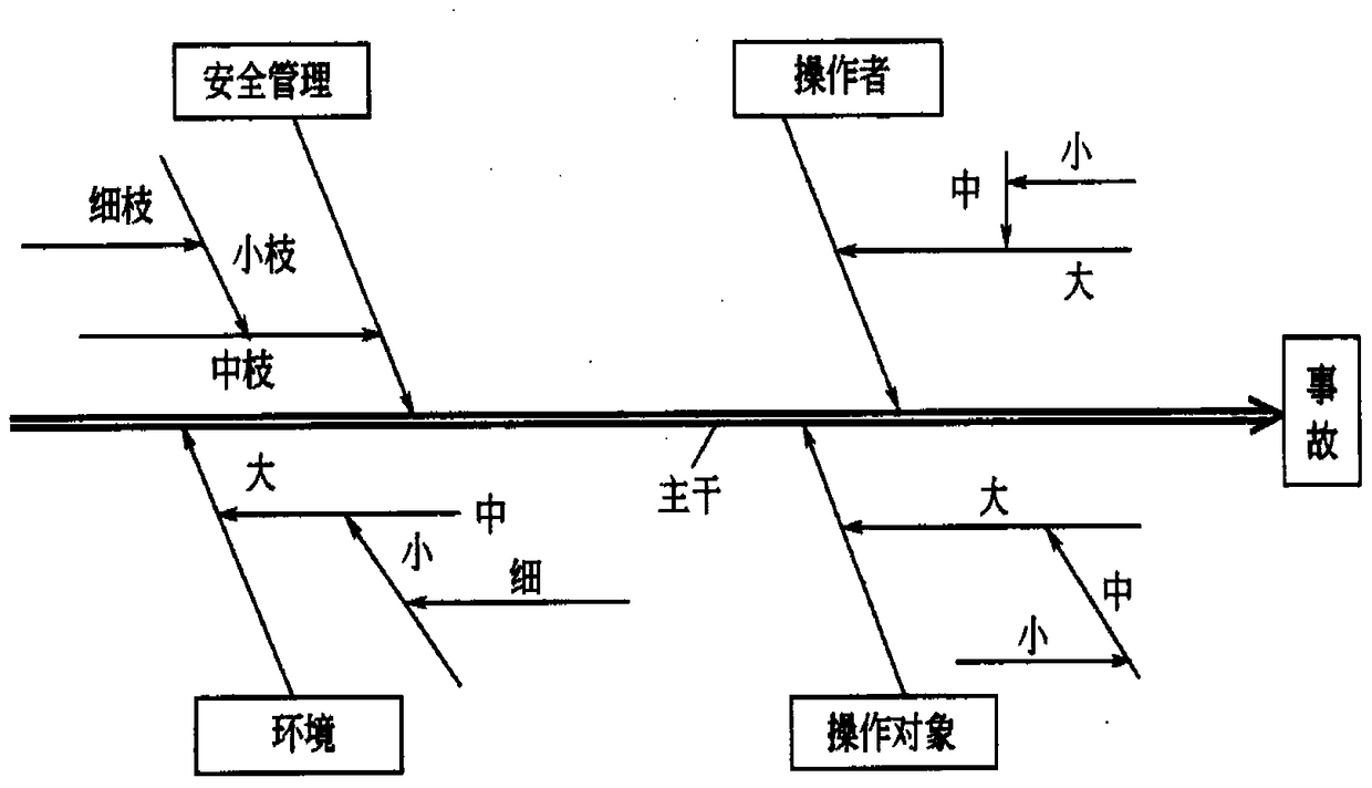
Although it is theoretically feasible to use the causal fishbone diagram in the computer field, it is too complicated for the process of artificial intelligence analysis and inference, and the causal relationship expressed is not rich enough
[0013] In summary, there are obviously inconveniences and defects in the actual use of the existing technology, so it is necessary to improve

Method used


Image

  • Method and system for implementing traceability based on monitoring points
  • Method and system for implementing traceability based on monitoring points
  • Method and system for implementing traceability based on monitoring points

Examples


example 1

[0113] Example 1: In the above table 2, it is necessary to find the abnormal point of the inference result of the abnormal point D, because there is only one xPath of the abnormal point D, and there is no "|" to connect the xPath, so directly obtain the xPath of the abnormal point D, and use it By performing string matching with the xPaths of other abnormal points that already exist in the one-way network traceability model, abnormal point B, abnormal point E, abnormal point F, and abnormal point I can be matched. The pushing process is as follows, the underlined part is the matched XPath substring when pushing.

[0114] D: A→D

[0115] Perform XPath string matching according to 'A→D', and match B, E, F, and I.

[0116] D: A→D ;

[0117] B: A→D → B;

[0118] E: A→D → E;

[0119] F: A→D →E→F|A→H→F;

[0120] I: A→C→I| A→D →B→I.

example 2

[0121] Example 2: In the above table 2, it is necessary to find the abnormal point of the inference result of the abnormal point I, first group the abnormal point I by "|" to obtain ["A→C→I", "A→D→B→I" ] array, and use each value of the array class to match the xPath of other abnormal points existing in the one-way network traceability model according to the string matching principle, and match all related abnormal points. The abnormal point that can be matched here is the abnormal point G. The inference process is as follows:

[0122] I: ["A→C→I", "A→D→B→I"]

[0123] In the first step, use 'A→C→I' to perform XPath string matching, and G can be matched.

[0124] I: A→C→I ;G: A→C→I →G|A→D→B→I→G

[0125] In the second step, use 'A→D→B→I' to perform XPath string matching, and the matching result is empty.

[0126] I: A→D→B→I

[0127] 2. How to solve the real abnormal source of multiple abnormal points?

[0128] For example: Receive abnormal point D, abnormal point B, ab...


PUM


Abstract

The application is suitable for the computer intelligent monitoring technical field, and provides a traceability realization method based on monitoring points; the method comprises the following steps: collecting abnormal causal relationship of each monitoring point; setting a one-way network traceability model according to the abnormal causal relationship of each monitoring point; determining an abnormal source corresponding to an abnormal point according to the one-way network traceability model when at least one monitoring point is monitored to be the abnormal point. Correspondingly, the application also provides a traceability realization system based on monitoring points; the one-way network traceability model is a prognosis type traceability model, and can combine a prognosis result with real conditions for grounding, thus fast and automatically positioning primary cause of the problems; the traceability realization method and system based on monitoring points are direct and visualized, high in virtual reality level, convenient in traceability calculation, strong in monitoring management ability, and can support complex logic relation description.

Description

technical field [0001] The present application relates to the technical field of computer intelligent monitoring, and in particular to a monitoring point-based traceability implementation method and system. Background technique [0002] At present, in the field of computer intelligent monitoring, there is a great need for a resource relationship model that can quickly construct the logical relationship between monitoring resources, and can quickly calculate the real source of abnormalities in monitoring resources based on the resource relationship model algorithm, so that the plan can be accurately executed. Achieve the effect from monitoring to intelligent control. Especially when monitoring the monitoring points of each facility (including hardware and software) in the data center, when a monitoring point reports a warning, due to the intricate relationship between the facilities, it is usually difficult to quickly locate the cause, because the original simple It is no lo...

Claims


Application Information

Patent Timeline
Patent Type & Authority Patents(China)
IPC IPC(8): G06F11/30
Inventor 张华
Owner ADVANCED NEW TECH CO LTD
Why Eureka
Try Eureka