
Bicycle braking system based on traffic signal lamp discrimination

A traffic signal light and brake system technology, which is applied in the field of bicycle brake systems, can solve problems such as difficult supervision

Active Publication Date: 2016-06-08
上海在赢端网络科技有限公司
View PDF7 Cites 3 Cited by
  • Summary
  • Abstract
  • Description
  • Claims
  • Application Information

AI Technical Summary

Problems solved by technology

[0002] As a convenient means of transportation, bicycles often have some hidden dangers while bringing convenience to people's daily life. In recent years, traffic accidents caused by bicycles running red lights and colliding with other motor vehicles are not uncommon. The punishment for the behavior of bicycles running red lights, but the punishment method still needs to rely on the traffic police on duty at the intersection to carry out on-site capture and punishment. In real life, at many intersections without police on duty, there will still be many bicycles breaking the law The act of running a red light occurs and is not easy to supervise

Method used


Image

  • Bicycle braking system based on traffic signal lamp discrimination
  • Bicycle braking system based on traffic signal lamp discrimination
  • Bicycle braking system based on traffic signal lamp discrimination

Examples


Embodiment 1

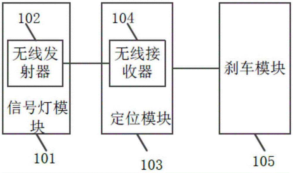
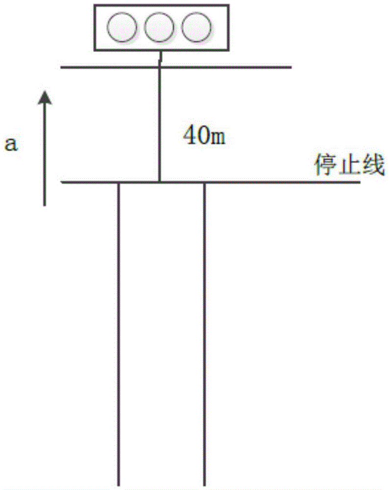
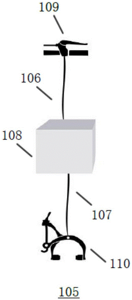
[0017] Please refer to figure 1 figure 2 as well as image 3 , figure 1 A structural schematic diagram of a bicycle braking system based on traffic signal identification provided by the present invention; figure 2 A schematic diagram of road planning at intersections provided by the present invention; image 3 It is a schematic structural diagram of the brake module provided by the present invention. Specifically, this embodiment provides a bicycle braking system based on traffic signal identification, which is used for non-motor vehicle lanes at intersections, including: a signal light module 101 located at one end of the road, used to obtain the display color of the signal light in real time and convert the corresponding electronic signal, and then wirelessly carry out real-time binding transmission of the electronic signal through the built-in wireless transmitter 102, wherein the effective signal transmission distance of the wireless transmitter 102 at least exceeds ...

Embodiment 2

[0022] This embodiment is basically the same as Embodiment 1, the difference is that in this embodiment, the positioning module 103 is also used to determine that the electronic signal is corresponding to the stop action when the signal light is green. That is, when the signal light shows green, the brake system does not brake the bicycle, and the bicycle can pass through the intersection normally.

Embodiment 3

[0024]This embodiment is basically the same as Embodiment 1, the difference is that in this embodiment, the signal light module 101 is also used to obtain the countdown time when the signal light shows green and convert it into real-time data and wrap it into the electronic signal, Before the positioning module 103 performs real-time positioning on the current driving position of the bicycle, it will also be used to judge whether the electronic signal is green corresponding to the signal light, and if so, judge whether the remaining countdown time is low according to the real-time data in the electronic signal If it is within the preset threshold, it will continue to act. Wherein, the preset threshold is set by the engineer, such as 5S, 10S, etc., preferably 5S here, that is, before the positioning module 103 performs real-time positioning on the current driving position of the bicycle, it will also judge whether the electronic signal is Corresponding to the signal light displ...


PUM


Abstract

The invention relates to a bicycle braking system based on traffic signal lamp discrimination. The bicycle braking system based on the traffic signal lamp discrimination comprises a signal lamp module, a positioning module and a braking module, wherein the signal lamp module is used for acquiring display color of a signal lamp in real time, converting the display color into a corresponding electronic signal and then carrying out real-time binding transmission on the electronic signal in a wireless manner by virtue of a built-in wireless transmitter; when a built-in wireless receiver receives the electronic signal transmitted by the wireless transmitter and judges that a corresponding signal lamp appears red or yellow, the positioning module is used for carrying out real-time positioning on the current travel position of a bicycle and generating positioning data, determining that the bicycle is in a travel state according to continuous change of the positioning data in a unit time and then producing and outputting a control signal; and the braking module comprises one electric cable winding device arranged between a first brake cable and a second brake cable and is used for controlling the second brake cable to be stretched to the utmost extent according to the control signal output by the positioning module, the first brake cable is connected with a brake lever, and the second brake cable is connected with at least one brake clamp.

Description

technical field [0001] The invention relates to the technical field of road traffic safety, in particular to a bicycle braking system based on traffic signal identification. Background technique [0002] As a convenient means of transportation, bicycles often have some hidden dangers while bringing convenience to people's daily life. In recent years, traffic accidents caused by bicycles running red lights and colliding with other motor vehicles are not uncommon. The punishment for the behavior of bicycles running red lights, but the punishment method still needs to rely on the traffic police on duty at the intersection to carry out on-site capture and punishment. In real life, at many intersections without police on duty, there will still be many bicycles breaking the law Running a red light happens and is not easy to monitor. [0003] Therefore, the inventor feels that the above-mentioned problem has the necessity of its improvement, and then, with its many years of creati...

Claims


Application Information

Patent Timeline
IPC IPC(8): G08G1/0967B62L3/02
CPCB62L3/026G08G1/0967
Inventor 钱月英
Owner 上海在赢端网络科技有限公司
Learn More