
Evacuation of membrane chamber

A technology of membrane and vacuum pumps, applied in the testing of fluid tightness, testing of machine/structural components, detection of fluid presence at leak points, etc.

Active Publication Date: 2019-08-09
INFICON INC
View PDF9 Cites 0 Cited by
  • Summary
  • Abstract
  • Description
  • Claims
  • Application Information

AI Technical Summary

Problems solved by technology

[0004] Smaller, lighter pumps are either only capable of high suction capacities or only reach low pressures, making them unsuitable alone as conventional pump replacements

Method used


Image

  • Evacuation of membrane chamber
  • Evacuation of membrane chamber
  • Evacuation of membrane chamber

Examples


Embodiment Construction

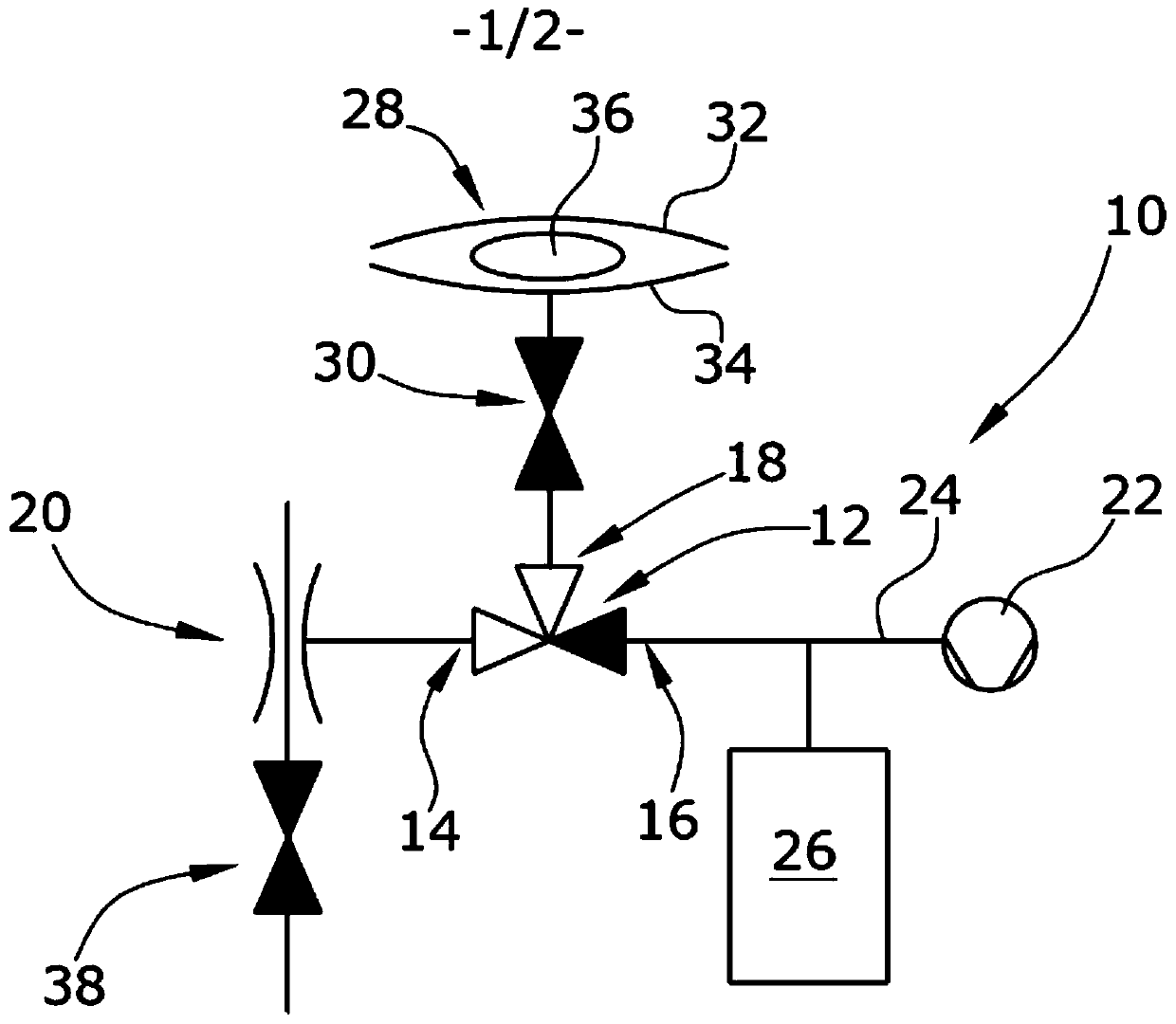
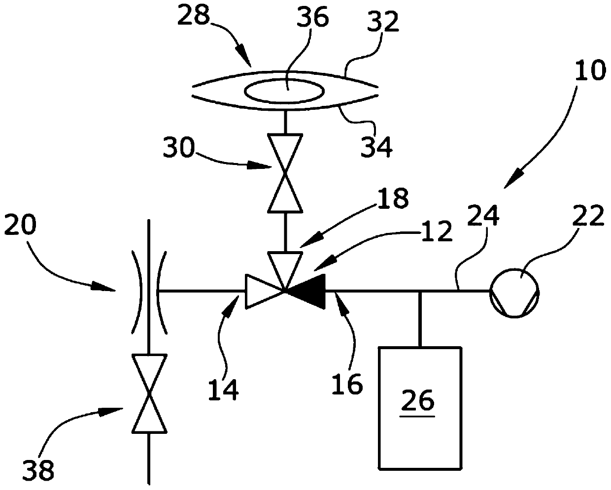
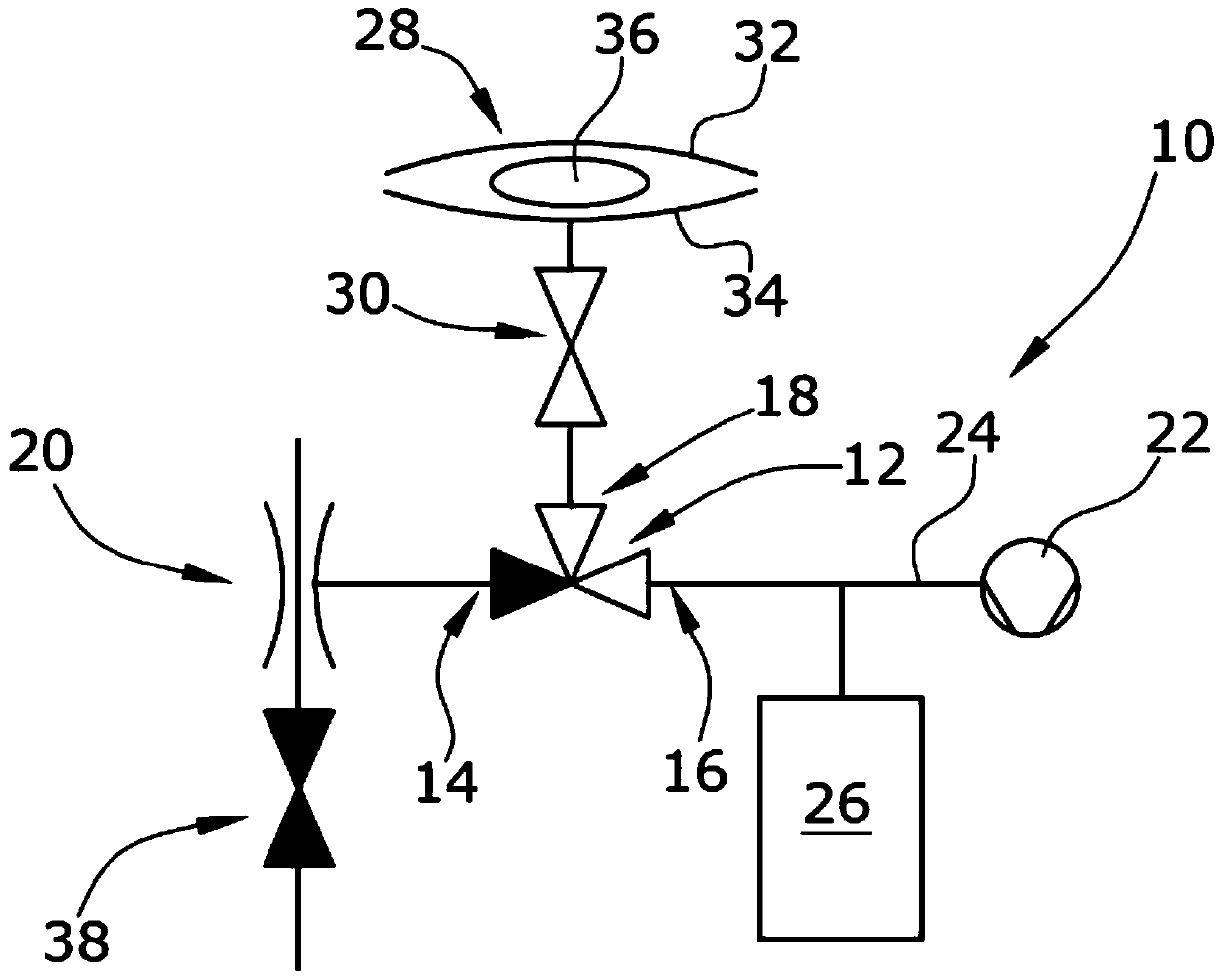
[0020] The central core component of the illustrated embodiment is a 3 / 2-way valve 12 with three ports 14, 16, 18 and two operating channels. A first vacuum pump 20 in the form of a Venturi pump is connected to said first port 14 . A second vacuum pump 22 in the form of a plunger pump is connected to said second port 16 . A line 24 connecting the second port 16 to the second vacuum pump 22 is connected by gas delivery to a buffer chamber 26 . The third port 18 is connected to the membrane chamber 28 by a line. A shut-off valve 30 is provided in the line between the membrane chamber 28 and the third port 18 . As an alternative, it is conceivable that each of the two vacuum pumps 20 , 22 is connected to the membrane chamber 28 via a respective separate line.

[0021] The film chamber 28 consists of two film layers 32 , 34 between which a sample 36 is arranged.

[0022] The Venturi pump 20 is connected to a valve 38 in order to be able to control the operation of the pump 20 ...


PUM


Abstract

The invention relates to a device (10) for evacuating a membrane chamber (28) using a pump system comprising at least two vacuum pumps (20, 22) designed for alternately evacuating the membrane chamber (28). The suction capacity of the first vacuum pump (20) in the device is greater than that of the second vacuum pump (22), and the final pressure obtainable with the first vacuum pump (20) is lower than with the The final pressure achievable by the second vacuum pump (22).

Description

technical field [0001] The invention relates to a device and a method for evacuating a membrane chamber. Background technique [0002] Membrane chambers are made of flexible, soft materials—mostly membranes—and are used to detect leaks in packages. Samples to be tested for leaks are placed in membrane chambers. In most cases, the samples were food packaging also made of flexible material. The membrane chamber surrounding the sample is evacuated. Afterwards, the pressure or gas within the membrane chamber is monitored in order to test the tightness of the sample and to detect possible leaks within the sample. [0003] Hitherto, membrane chambers have been evacuated with vacuum pumps having a high suction capacity and reaching low end pressures. Such pumps are heavy and require high electrical power to work. [0004] Smaller, lighter pumps are either only capable of high suction capacities or only reach low pressures, so they are not suitable alone as a replacement for co...

Claims


Application Information

Patent Timeline
Patent Type & Authority Patents(China)
IPC IPC(8): G01M3/22G01M3/20F04B41/06
CPCG01M3/205G01M3/229F04F5/22F04F5/44F04F5/54
Inventor 西尔维奥·德克尔迈克尔·道恩豪尔丹尼尔·维茨格亚尔马尔·布鲁恩斯
Owner INFICON INC
Learn More