
A damping mechanism for deploying an antenna

A damping mechanism and damping technology, which is applied in the field of damping and damping mechanisms, can solve the problems of the damping design and parameter optimization of the damping and damping mechanism, and the inability to control the vibration modes of each order of the antenna separately, so as to achieve good vibration suppression effect, The effect of enhancing the carrying capacity and simple control method

Active Publication Date: 2014-08-13
BEIJING INST OF SPACECRAFT SYST ENG
View PDF0 Cites 6 Cited by
  • Summary
  • Abstract
  • Description
  • Claims
  • Application Information

AI Technical Summary

Problems solved by technology

However, the two sets of dampers of the damping and vibration reduction mechanism used by SRTM cannot control the vibration modes of each order of the deployed antenna separately. When adjusting the damping parameters to control the vibration of a certain order mode, it is easy to affect other order modes. The vibration control effect brings great difficulties to the damping design and parameter optimization of the damping and vibration reduction mechanism of the unfolded antenna.

Method used


Image

  • A damping mechanism for deploying an antenna
  • A damping mechanism for deploying an antenna
  • A damping mechanism for deploying an antenna

Examples


Embodiment Construction

[0025] In order to fully illustrate the characteristics of the present invention and the mode of carrying out the present invention, examples are given below.

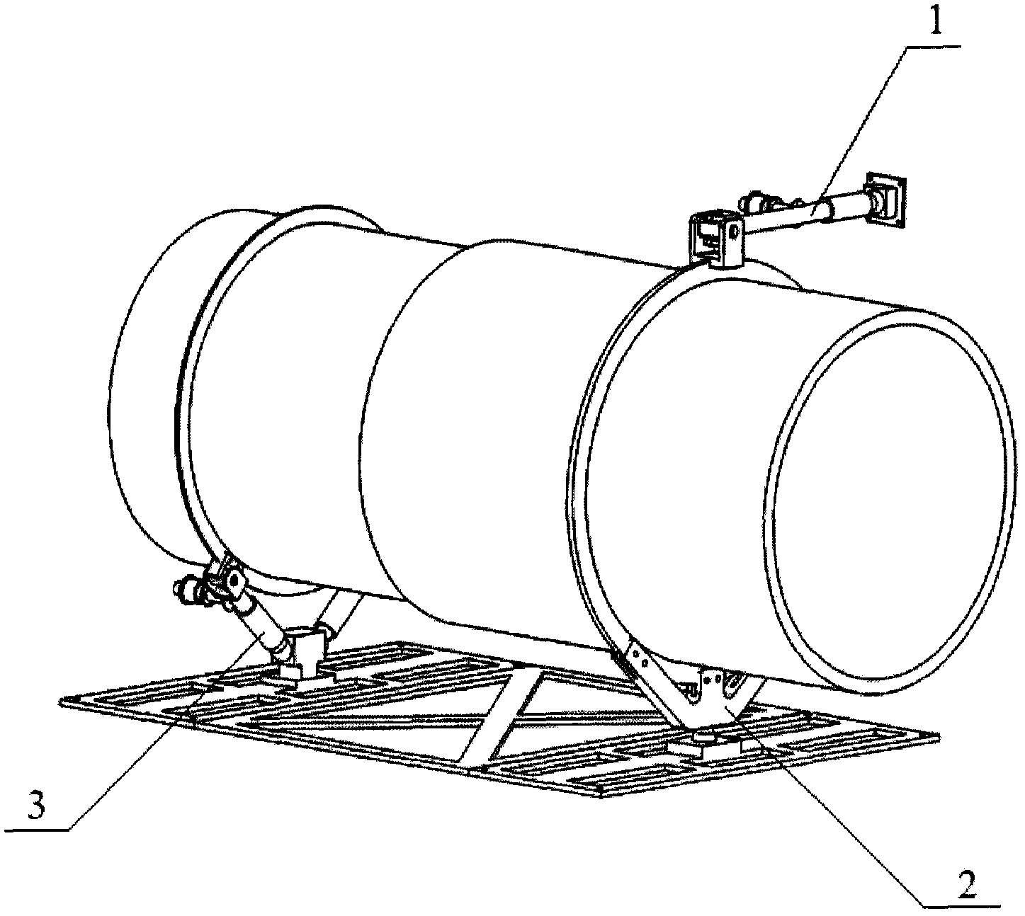
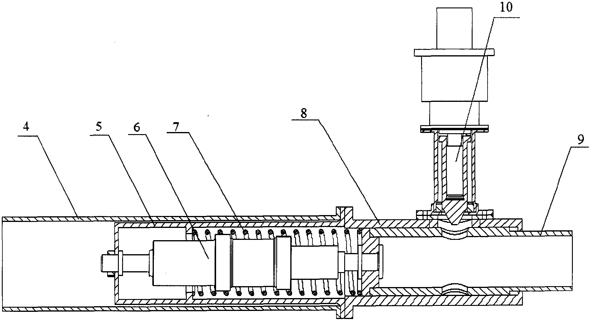
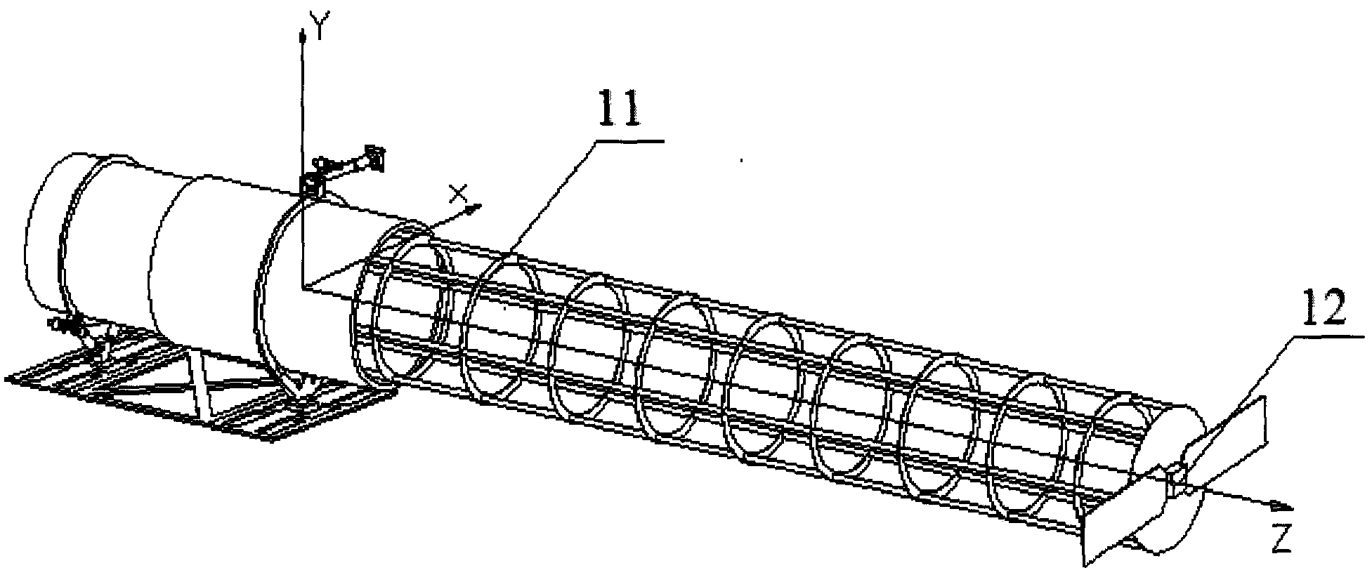
[0026] like figure 1 Shown, a kind of damping and vibration reduction mechanism of deploying antenna, described damping and vibration reduction mechanism is installed on the antenna support tube of the root of spacecraft deployment antenna; Composed of curved damping rods 3, the spacecraft is a satellite.

[0027]Wherein, the front end of the antenna support tube is the direction in which the antenna is deployed. The front end of the torsional damping rod 1 is installed on the upper side of the front end of the antenna support tube through a universal joint, which can realize the rotation of two degrees of freedom; the rear end of the torsional damping rod 1 is connected with the satellite side wall structure through a ball joint, which can realize three Rotation of degrees of freedom; the satellite side wall structu...


PUM


Abstract

The invention relates to a damping and vibration reduction mechanism for deploying an antenna. In the damping and vibration reduction mechanism, the front end of the torsional damping rod is installed on the upper side of the front end of the antenna support cylinder through a universal joint, and the rear end is connected to the side wall structure of the spacecraft through a ball joint. ; The rigid support seat and the torsional damping rod are located at relative positions on the same cross-section of the antenna support tube, one end is fixedly connected to the bottom of the front end of the antenna support tube, and the other end is connected to the mounting structure at the bottom of the spacecraft through a ball joint; two curved damping rods are installed symmetrically At the bottom of the rear end of the antenna support cylinder, one end is connected to the antenna support cylinder through a universal joint, and the other end is connected to the bottom mounting structure of the spacecraft through a ball joint. The damping and vibration reduction mechanism controls the torsional and bending mode vibrations of the unfolded antenna separately through the torsional damping rod and the bending damping rod, which is convenient for adjusting the damping characteristics of each order mode of the unfolded antenna. The control method is simple and the vibration suppression effect is good; The locking and releasing device has the functions of launch bearing and on-orbit damping and vibration reduction.

Description

technical field [0001] The invention relates to a damping and vibration reduction mechanism for deploying antennas, in particular to a damping and vibration reduction mechanism mainly used for on-rail vibration reduction of deployment antennas, and the damping and vibration reduction mechanism is installed on the support cylinder at the root of the deployment antenna . Background technique [0002] With the development of spacecraft technology, deployable antennas, that is, antennas with deployable functions, such as large deployable satellite antennas and large flexible truss antennas, are gaining more and more applications. The structure of the unfolded antenna has the advantages of small folded volume, large unfolded size, light weight and high strength. But at the same time, due to the light weight, large deflection and weak self-damping of the deployed antenna, once it is disturbed by some vibration equipment on the spacecraft during the orbit, it is easy to arouse its...

Claims


Application Information

Patent Timeline
IPC IPC(8): F16F13/04H01Q1/08
Inventor 罗敏徐青华王耀兵於晓榛
Owner BEIJING INST OF SPACECRAFT SYST ENG
Learn More