Automatic correction device and correction method for moving arm

A boom and automatic technology, which is applied in the direction of manufacturing tools, metal processing, metal processing equipment, etc., can solve the problems of difficult to guarantee accuracy, high labor cost, and low correction accuracy, so as to achieve good accuracy, reduce labor cost, and improve correction quality effect

Active Publication Date: 2016-06-15
GUANGXI UNIVERSITY OF TECHNOLOGY
View PDF6 Cites 5 Cited by
  • Summary
  • Abstract
  • Description
  • Claims
  • Application Information

AI Technical Summary

Problems solved by technology

Workers rely on experience to determine the push-out distance of the oil cylinder, and use a tape measure to ensure that the total length between the two boom plates meets the correction requirements. This correction method is labor-intensive, high in labor costs, low in correction accuracy, and low in production efficiency.
When the boom is corrected, the measurement is performed first. The measurement is generally made by combining a steel ruler to manually measure the size. Repeated measurement, the accuracy is difficult to guarantee
Therefore, the distance test and correction between the two boom plates need to be repeated, and the efficiency is low

Method used


Image

  • Automatic correction device and correction method for moving arm
  • Automatic correction device and correction method for moving arm

Examples


Embodiment 1

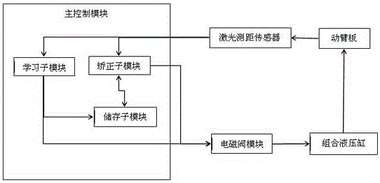
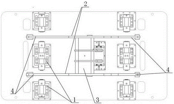
[0031] Such as figure 1 As shown, the automatic boom correction device provided by the present invention includes a main control module, a laser ranging sensor, a battery valve module, and a hydraulic cylinder combination;

[0032] The main control module is electrically connected to the laser ranging sensor and the battery valve module; the laser ranging transmitter is aligned with each boom plate of the boom to obtain the position of each boom plate; the hydraulic cylinder group is based on There are multiple groups of boom plate correction directions, each group of hydraulic cylinders corresponds to one boom plate correction; the battery valve module is combined with the hydraulic cylinder, and each group of hydraulic cylinders has a corresponding battery valve installed on the oil circuit;

[0033] The laser distance measuring sensor transmits the detected position information of each boom plate to the main control module;

[0034] The main control module compares the position in...

Embodiment 2

[0041] The automatic boom correction device provided by the present invention includes a main control module, a laser ranging sensor, a battery valve module, and a hydraulic cylinder combination;

[0042] The main control module includes a learning sub-module and a correction sub-module. The learning sub-module is electrically connected to a laser ranging sensor, a battery valve module, and a storage sub-module; the correction sub-module is connected to the laser ranging sensor and a battery Electrical connection of valve module and storage sub-module;

[0043] When the correction is performed for the first time or the correction parameters are revised again, the learning sub-module is first started; the laser ranging sensor transmits the detected position information of each boom plate to the learning sub-module; the learning sub-module performs position information and prediction The set standard position range value is compared. If it exceeds the standard position range value, t...


PUM


Abstract

The invention discloses an automatic correction device for a moving arm. The automatic correction device comprises a master control module, a laser distance measuring sensor, a battery valve module and a hydraulic cylinder assembly. The master control module is electrically connected with the laser distance measuring sensor and the battery valve module. The laser distance measuring sensor is aligned to all moving arm plates of the moving arm and obtains the positions of all the moving arm plates. A plurality of hydraulic cylinder sets are arranged according to the moving arm plates needing to the corrected. The battery valve module is connected with the hydraulic cylinder assembly. The laser distance measuring sensor detects the position information of all the moving arm plates. The master control module compares the position information with a preset standard position range value and transmits correction distance parameters to the battery valve module. The feeding strokes of hydraulic cylinders are controlled by the battery valve module, and therefore the positions of all the moving arm plates are corrected. According to the automatic correction device, the correction technology of the moving arm of a loader is intelligently controlled, and the problems that in original manual correction, the labor intensity is large, the manual cost is high, and the correction precision and the production efficiency are low are solved.

Description

Technical field [0001] The invention relates to the technical field of mechanical engineering, in particular to an automatic correction device and a correction method for a boom. Background technique [0002] At present, almost all loader and excavating boom correction methods are manual correction. Workers rely on experience to determine the pushing distance of the cylinder, and rely on a tape measure to ensure that the total length between the two boom plates meets the correction requirements. This correction method is labor intensive, high in labor costs, low in correction accuracy, and low in production efficiency. When the boom is rectified, the measurement is performed first. The measurement generally uses a combination of steel rulers to manually measure the size. Repeated measurement is difficult to ensure the accuracy. Therefore, the distance test and correction between the two boom plates need to be repeated, and the efficiency is low. The total time for each boom cor...

Claims


Application Information

Patent Timeline
Patent Type & Authority Applications(China)
IPC IPC(8): B21D1/12B21C51/00
CPCB21C51/00B21D1/12
Inventor 徐武彬花庆宝李冰莫琦李慧琼梁蔓安王国安诸葛丽蓉庞贤剑孙云飞王俊梁解向阳
Owner GUANGXI UNIVERSITY OF TECHNOLOGY
Why Eureka
Try Eureka