
Separating component

A component and trough technology, applied in the field of material distribution equipment, can solve the problems of damaging the bushing surface, not having the function of material distribution, and not being able to detect whether there is a bushing in the trough, and achieve the effect of fast and accurate material distribution

Inactive Publication Date: 2016-06-15
BOZHON PRECISION IND TECH CO LTD
View PDF7 Cites 5 Cited by
  • Summary
  • Abstract
  • Description
  • Claims
  • Application Information

AI Technical Summary

Problems solved by technology

[0002] When pressing the bushing onto the product, the bushing is supplied to the trough of the positioning seat through the feeding pipe. There are multiple sets of bushings adjacent to each other in the feeding pipe, and the bushing needs to be pressed before pressing. Separate them one by one and send them to the bushing seat. The existing technology does not have the function of material distribution. The bushes in the trough are directly pushed out of the chute for material distribution. In this way, the material distribution will cause two adjacent bushes up and down. There is friction between them and the surface of the bushing is damaged, and sometimes it is impossible to detect whether there is a bushing in the trough, which brings inconvenience to the subsequent installation

Method used


Image

  • Separating component
  • Separating component
  • Separating component

Examples


Embodiment Construction

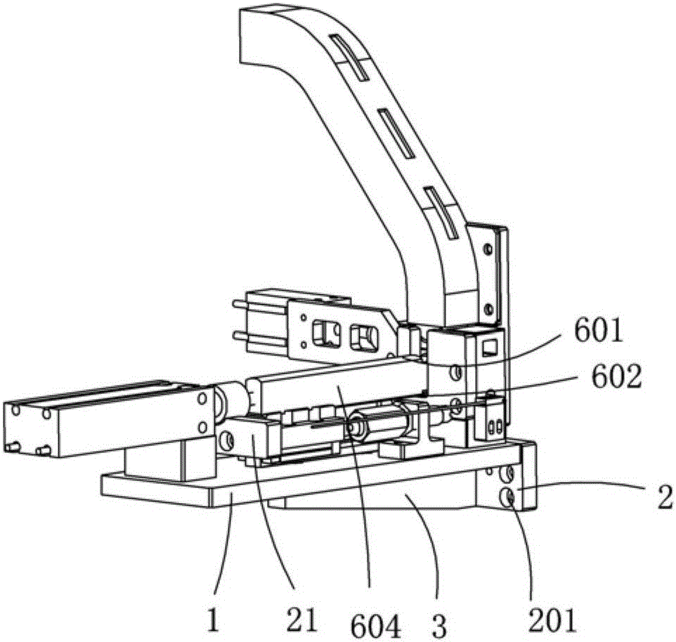
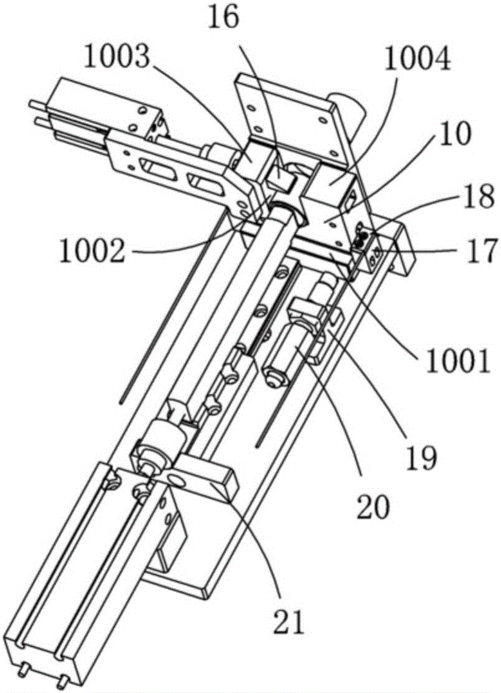
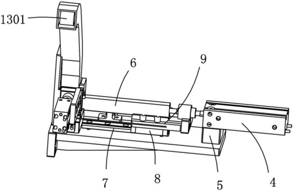
[0021] Examples, see attached Figure 1~5 , a material distribution assembly, including a fixed seat and a pushing drive device installed on the fixed seat, the fixed seat includes a fixed plate 1, a mounting block 2 installed with the end of the fixed plate 1, and a mounting block 2 installed on the fixed plate 1 and installed Rib 3 between blocks 2. In this embodiment, the fixed plate 1 is a flat plate structure, the fixed plate 1 is installed in a horizontal state, the fixed plate 1 and the installation block 2 are installed vertically, the installation block 2 is installed on the left side of the fixed plate 1, and the upper The surface is flush with the upper surface of the fixing plate 1, and the mounting block 2 is provided with a mounting hole 201, through which the mounting block 2 can be fixed on other equipment by screwing, so as to facilitate the fixing of the whole mechanism. There is one group of reinforcing ribs, which are arranged in the middle of the fixed pl...


PUM


Abstract

The invention relates to a material distributing assembly, a material pushing cylinder is installed on a fixed seat, a material pushing rod is installed on the material pushing cylinder, a sliding guide assembly is installed on the fixing seat, and the pushing rod is installed on the sliding guiding assembly; the fixing seat is equipped with a positioning seat; the right side of the positioning seat is provided with a boss, and the boss is equipped with a stopper block that limits the sliding of the bushing, and the push rod can pass through the stopper block; on the fixed seat and on the left side of the positioning seat, there is a The runner plate through which the sleeve passes; the positioning seat is provided with a trough capable of accommodating the bushing, and the upper part of the positioning seat is equipped with a feed pipe connected with the trough; the right side of the positioning seat is equipped with a distribution cylinder fixed block Cylinder, the front end of the material distribution cylinder is equipped with a material distribution block, and the material distribution block passes through the positioning seat and can extend into the material trough; the optical fiber is installed on the fixed seat through the optical fiber fixed seat. The optical fiber of the present invention senses the incoming material of the bushing, and the material distribution cylinder drives the material distribution block to push out to separate the two bushes; the pushing cylinder moves to push the next bushing into the flow channel plate.

Description

Technical field: [0001] The invention relates to the field of material distribution equipment, in particular to a material distribution component that separates two adjacent bushes. Background technique: [0002] When pressing the bushing onto the product, the bushing is supplied to the trough of the positioning seat through the feeding pipe. There are multiple sets of bushings adjacent to each other in the feeding pipe, and the bushing needs to be pressed before pressing. Separate them one by one and send them to the bushing seat. The existing technology does not have the function of material distribution. The bushes in the trough are directly pushed out of the chute for material distribution. In this way, the material distribution will cause two adjacent bushes up and down. There is friction between them and the surface of the bushing is damaged, and sometimes it is impossible to detect whether there is a bushing in the trough, which brings inconvenience to the subsequent ...

Claims


Application Information

Patent Timeline
IPC IPC(8): B23P19/00
CPCB23P19/003
Inventor 吕绍林陈小刚叶飞颜政李祖明张蒙陈丽丽
Owner BOZHON PRECISION IND TECH CO LTD
Learn More