
Coloring inspection apparatus and coloring inspection method

Active Publication Date: 2016-05-19
PAPALAB
View PDF7 Cites 14 Cited by
  • Summary
  • Abstract
  • Description
  • Claims
  • Application Information

AI Technical Summary

Benefits of technology

The invention allows for accurate and easy analysis of color information in the coloring field. This can be used to inspect the texture and fine color tint of products, humans, and other objects. The invention reduces the time needed for computations and has a wide range of applications and high industrial availability.

Problems solved by technology

For example, with regard to automobiles, the proposed techniques of Non-Patent Literatures 1 to 5 are not yet sufficient as the countermeasure for flip flop or the like.
The variation of color is expanded unlimitedly and causes a difficulty in color inspection.
Additive color mixing, however, does not allow for subtraction of lights.
It is accordingly difficult to handle the negative value of spectral sensitivity.
Such approximation, however, does not enable the color in the color gamut of the human eye to be accurately detected and may cause color drift or color collapse of the image or the video image.
It is empirically known that dark colors make dirt and damage on the coating surface easily noticeable.
But this method has not been widely used.

Method used


Image

  • Coloring inspection apparatus and coloring inspection method
  • Coloring inspection apparatus and coloring inspection method
  • Coloring inspection apparatus and coloring inspection method

Examples


embodiment 1

of imaging the boundary of panels of an automobile 5 with the camera 2 of the invention;

[0055]FIG. 14 is a perspective view illustrating Example 2 of imaging the boundary of panels of the automobile 5 with the camera 2 according to Embodiment 1 of the invention;

[0056]FIG. 15 is a perspective view illustrating Example 3 of imaging the boundary of panels of the automobile 5 with the camera 2 according to Embodiment 1 of the invention;

[0057]FIG. 16 is a perspective view illustrating Example 4 of imaging the boundary of panels of the automobile 5 with the camera 2 according to Embodiment 1 of the invention;

[0058]FIG. 17 is a perspective view illustrating Example 5 of imaging the boundary of panels of the automobile 5 with the camera 2 according to Embodiment 1 of the invention;

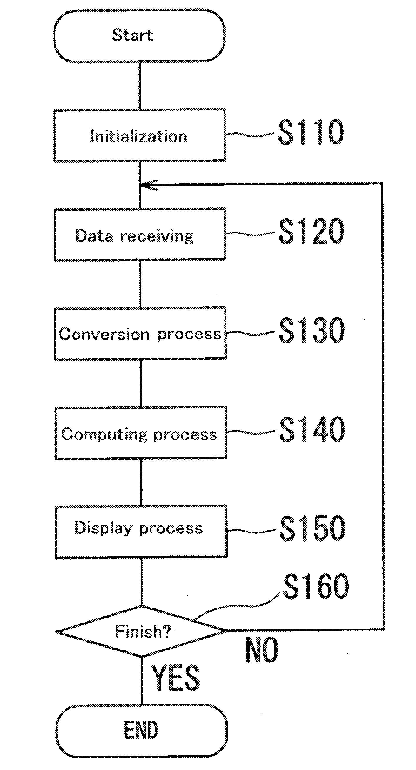
[0059]FIG. 18 is a flowchart showing a processing flow by an arithmetic processing unit 3 according to Embodiment 1 of the invention;

[0060]FIG. 19 is a sub-flowchart showing a sub-flow by the arithmetic processin...

embodiment 2

[0063]FIG. 22 is a block diagram illustrating the configuration of a coloring inspection apparatus 101 of the invention;

[0064]FIG. 23 is a flowchart showing a processing flow by an arithmetic processing unit 103 in the coloring inspection apparatus 101 according to Embodiment 2 of the invention;

embodiment 3

[0065]FIG. 24 is a block diagram illustrating the configuration of a coloring inspection apparatus 201 of the invention;


PUM


Abstract

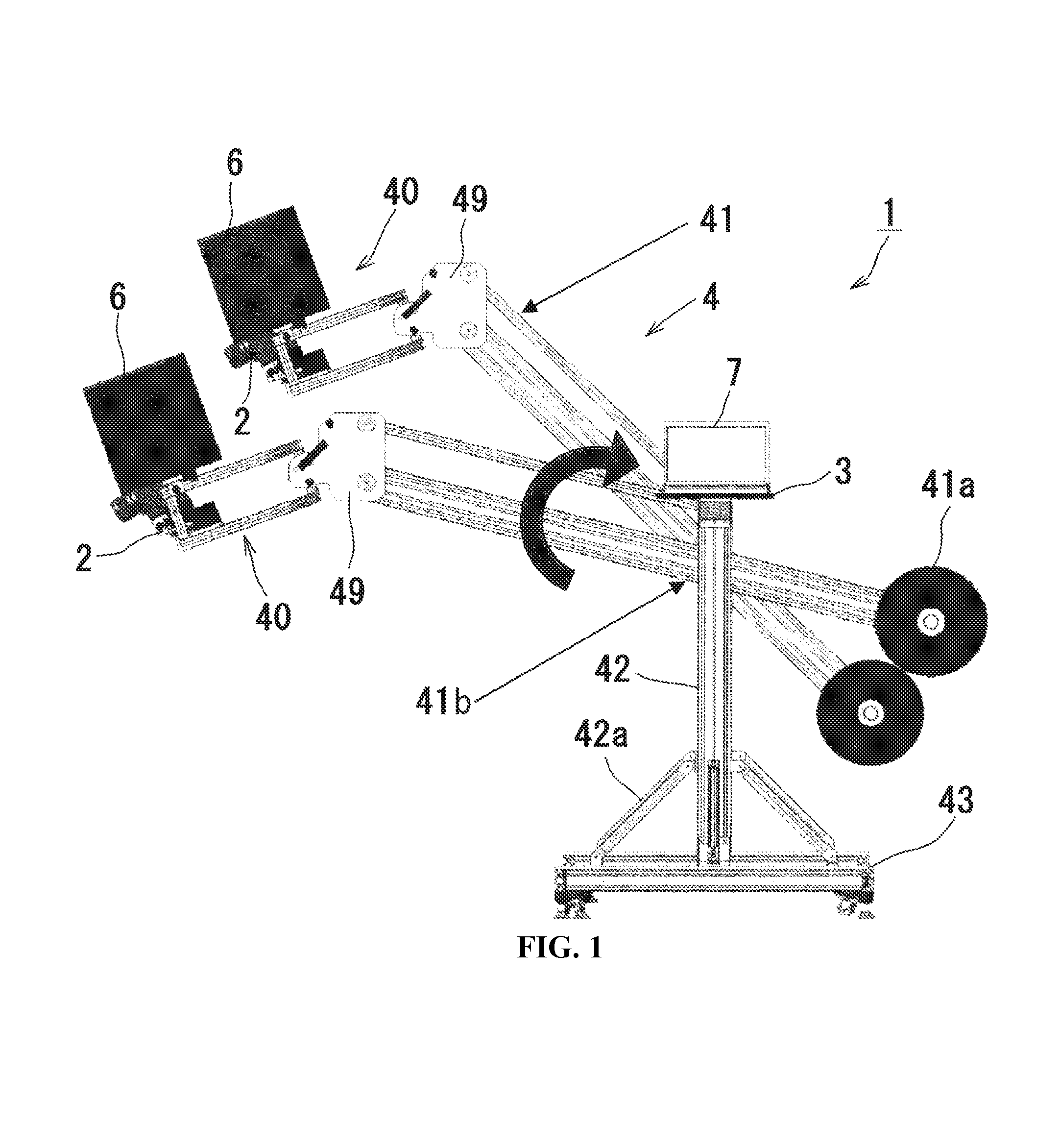
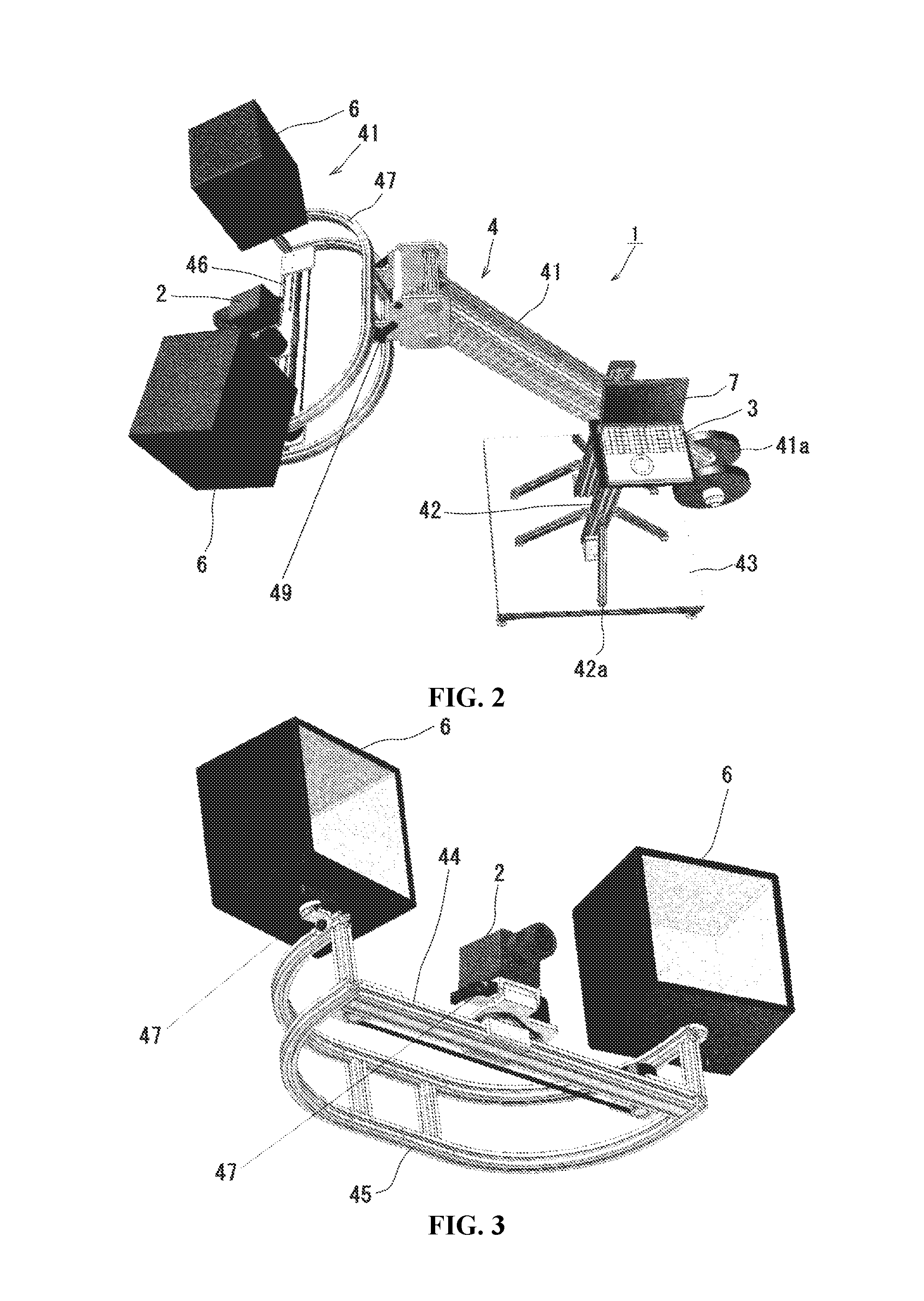
An object is to ensure clear and easy quantification of the textures such as metallic texture and shiny texture of pearl pigment and to rationalize comparison inspection between an inspection object and a reference object. A coloring inspection apparatus 1 includes a camera 2 that is configured to have three spectral sensitivities (S1(λ), S2(λ), S3(λ)) linearly and equivalently converted to a CIE XYZ color matching function, an arithmetic processing unit 3 that is configured to obtain and compute coloring data by conversion of an image which has three spectral sensitivities and is obtained by the camera 2 into tristimulus values X, Y and Z in a CIE XYZ color system, and lighting units 6 that are configured to illuminate an automobile 5 as an example of measuring object. The coloring inspection apparatus 1 computes a color distribution consistency index that represents a ratio of overlap of two xyz chromaticity histogram distributions of an inspection object Q and a reference object R, so as to inspect color.

Description

TECHNICAL FIELD[0001]The present invention relates to a coloring inspection apparatus and a corresponding method of inspecting the color distribution of an image for evaluation of coating of a commercial product.BACKGROUND ART[0002]Various commercial products, for example, electric appliances, vehicles such as automobiles, housing and building products, electric appliances, and clothes, need coating or coloring. Such commercial products are coated and colored in the manufacturing process. The appearance color is an important factor for selection of a commercial product in the sales process.[0003]For example, with regard to automobiles, the proposed techniques of Non-Patent Literatures 1 to 5 are not yet sufficient as the countermeasure for flip flop or the like. Release of every new model car continues to increase the number of outer panel colors. The user needs for the color become diversified. New colors are often set in the case of facelift or for specially equipped cars. Automob...

Claims


Application Information

Patent Timeline
IPC IPC(8): G06T7/40G06K9/62H04N5/225G06T7/00H04N9/64G06K9/46G06V10/50G06V10/56
CPCG06T7/408H04N9/64G06K9/4652G06K9/6201G06T7/0004H04N5/2251G06K9/4642H04N5/2256G01J3/504G01J3/0202G01J3/462G01J3/50G01J2003/2813G01J3/10G01J3/51G01J3/465G06T7/90G06T2207/30156G06V10/50G06V10/56H04N23/50H04N23/80G06T7/001G06T2207/10024G06F18/22H04N23/56
Inventor KATO, MAKOTO
Owner PAPALAB
Learn More