Automatic material separating mechanism of cam

A material distribution mechanism and cam technology, applied in the direction of pile separation, object separation, thin material processing, etc., can solve the problems of high labor intensity, increased production cost, low efficiency, etc., achieve high work efficiency, reduce labor intensity, and distribute fast and accurate results

Active Publication Date: 2014-07-30
BOZHON PRECISION IND TECH CO LTD
View PDF5 Cites 17 Cited by
  • Summary
  • Abstract
  • Description
  • Claims
  • Application Information

AI Technical Summary

Problems solved by technology

[0002] For some irregular-shaped sheet parts, they need to be loaded one by one during the feeding process, and these sheet parts are generally placed in the magazine, and need to be taken out of the magazine one by one during the feeding process, due to their thin thickness , the process of taking it out from the magazine is time-consuming and laborious, the labor intensity of the workers is high, the efficiency is low, and the production cost is also increased

Method used


Image

  • Automatic material separating mechanism of cam
  • Automatic material separating mechanism of cam
  • Automatic material separating mechanism of cam

Examples


Embodiment Construction

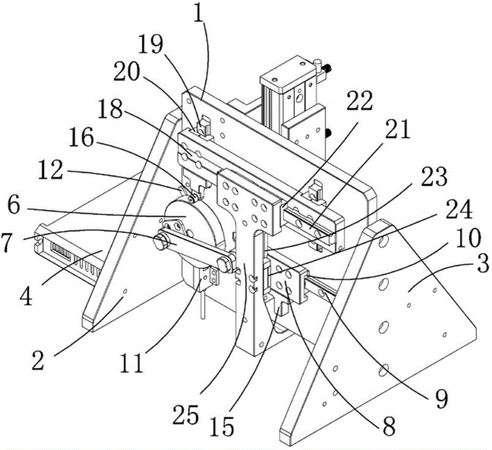
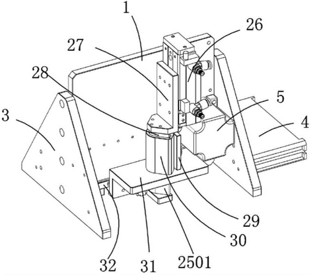
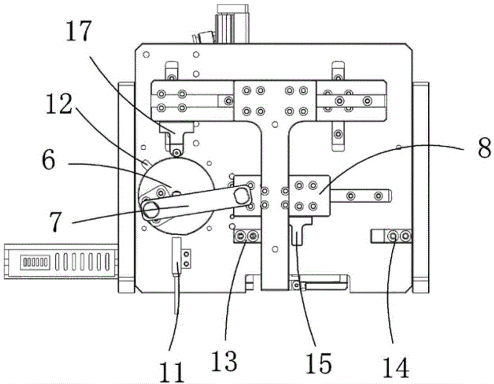
[0022] Examples, see attached Figure 1~4 , a cam automatic material distribution mechanism, which includes a mounting plate 1, a left support plate 2, a right support plate 3, a cam linkage mechanism, a cam follower mechanism and a material extrusion mechanism, the left and right sides of the mounting plate A left support plate and a right support plate are respectively fixedly installed;

[0023] Described cam link mechanism comprises stepper driver 4, stepper driver 5, cam 6, cam link 7, cam plate 8, transverse slide rail 9, transverse slide block 10, rotary photoelectric sensor 11 and induction plate 12, so The stepper driver is located on the left side of the left support plate, the stepper driver is installed on the right side of the left support plate, and a cam is installed on the stepper driver; A horizontal slider is installed in conjunction with a cam plate installed on the horizontal slider; one end of the cam link is connected with the cam, and the other end is c...


PUM


Abstract

The invention relates to an automatic material separating mechanism of a cam. The automatic material separating mechanism is characterized in that a stepping driving machine is driven by a stepping driver, thus the cam is driven to rotate, and a cam connecting rod is driven for enabling a cam plate to move left and right on a transverse sliding rail; when the cam rotates, a rolling wheel is driven to lift, thus a lifting plate is driven to lift by a follower plate, and a connecting plate can be finally lifted; a material pushing plate is driven to be downwards pressed by an air cylinder, the material pushing plate is used for downwards pressing a material in a material box, the material is pressed out from the lower part of the material box and enter a through hole of a positioning plate, since the connecting plate can move in the horizontal direction and the vertical direction, a top block can be lifted in the through hole of the positioning plate in the vertical direction, a material tank is formed when the top block descends, the depth of the material tank is higher than the thickness of the material, the material enters the material tank after the material is pressed out from the through hole, the positioning plate is driven to horizontally move out in the sliding rail direction and get away from the position where the material box is located, meanwhile, the material is ejected out from the material tank by upwards ejecting the top block of the connecting plate, the material is taken away by other mechanisms, the positioning plate returns to the lower end of the material box again, the cam rotates in a circle, and one material is pressed.

Description

Technical field: [0001] The invention relates to the field of material distributing mechanism equipment, in particular to a cam automatic material distributing mechanism. Background technique: [0002] For some irregular-shaped sheet parts, they need to be loaded one by one during the feeding process, and these sheet parts are generally placed in the magazine, and need to be taken out of the magazine one by one during the feeding process, due to their thin thickness , The process of taking it out from the magazine is time-consuming and labor-intensive, the labor intensity of the workers is high, the efficiency is low, and the production cost is also increased. Invention content: [0003] The object of the present invention is to address the shortcomings of the prior art and provide a cam automatic material distributing mechanism, which can automatically take out parts one by one from the magazine, and the material distributing is fast, accurate and efficient. [0004] Tec...

Claims


Application Information

Patent Timeline
Patent Type & Authority Applications(China)
IPC IPC(8): B65G47/82B65H3/00
Inventor 吕绍林马金勇赵永存孙卫东郭文龙刘治渊
Owner BOZHON PRECISION IND TECH CO LTD
Why Eureka
Try Eureka