Multi-rotor aircraft

A multi-rotor aircraft and rotor technology, applied in the field of aircraft, can solve the problems that are not conducive to the space layout of the fuselage, cannot quickly control the flight attitude of multi-rotor aircraft, and have low safety, so as to achieve flexible adjustment of aircraft flight attitude and benefit the machine Body layout, high flight safety effect

Inactive Publication Date: 2016-06-15
刘海涛
View PDF5 Cites 9 Cited by
  • Summary
  • Abstract
  • Description
  • Claims
  • Application Information

AI Technical Summary

Problems solved by technology

However, compared with the motor, the biggest disadvantage of the fuel engine is the slow response speed, which cannot meet the requirements of quickly controlling the flight attitude of the multi-rotor aircraft.
In addition, when a multi-rotor aircraft has a rotor failure, the general result is the crash of the aircraft. If the cargo on the aircraft is more expensive or even passengers are carried on the aircraft, it will cause irreparable losses.
[0004] For the solution of using oil-electric hybrid power to solve the endurance of multi-rotor aircraft, most of them adopt the method of variable pitch of the rotor, which is affected by the accuracy of the steering gear and the environment, and the jitter is relatively large
There are also solutions that use one engine and then transmit power to each rotor through a transmission mechanism. This method has a complex structure, low efficiency, and high failure rate, which is not conducive to the space layout of the fuselage.
Moreover, once the engine fails, the rotors connected through the transmission mechanism will fail, which is very easy to cause a crash, and the safety is relatively low

Method used


Image

  • Multi-rotor aircraft
  • Multi-rotor aircraft
  • Multi-rotor aircraft

Examples


Embodiment Construction

[0024] The present invention will be described in detail below in conjunction with the accompanying drawings and specific embodiments.

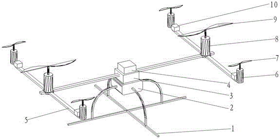
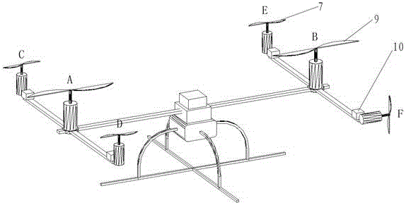
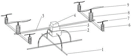
[0025] like figure 1 As shown, the present embodiment 1 provides a multi-rotor aircraft, a fuel tank 2 is assembled and connected to the landing gear 1, a battery box 3 is assembled and connected to the fuel tank, a control box 4 is assembled and connected to the battery box, and a control box 4 is assembled and connected to the battery box. Fuselage support 5, two vertically installed power rotors 9 are symmetrically distributed at both ends of the fuselage support 5, and the two power rotors 9 are respectively set with positive and negative paddles. torque. Each powered rotor 9 is driven by a separate engine 8 . At the outer end of the fuselage support 5, four motor-driven vertical attitude rotors 7 are symmetrically distributed. The diagonally distributed attitude rotors are both positive or reverse, and the four attitude rotors have the...


PUM


Abstract

The invention provides a multi-rotor aircraft.The multi-rotor aircraft comprises two power rotors driven by independent engines and four or more attitude rotors driven by motors.The power rotors mainly supply flight power, and the rotating speed of the power rotors is relatively constant.The attitude rotors are controlled by a control box flight control system to flexibly adjust the flight attitude.The multi-rotor aircraft has the advantages that the fuel engines are adopted as main power, the duration of flight is long, and meanwhile the rotors driven by the motors are adopted for flexibly adjusting the flight attitude.The number of the normal rotation rotors is equal to that of the reverse rotation rotors, torque on a fuselage is offset mutually, control is simplified, and energy is saved.Through the arrangement of the two engines, the flight power can be improved, a complicated transmission mechanism is avoided, efficiency is improved, fuselage arrangement can be improved, emergency landing can be realized under the cooperation of a steering engine when any engine or motor breaks down, and safety is higher.

Description

technical field [0001] The invention relates to the technical field of aircraft, in particular to a multi-rotor aircraft. Background technique [0002] Multi-rotor aircraft is an aircraft with simple structure, flexible control and stable flight attitude. Generally, there are different types such as three-axis, four-axis, six-axis, and eight-axis. Thanks to the development of micro-electromechanical and sensor technologies in recent years, multi-rotor aircraft have been widely used in fields such as model aircraft and aerial photography platforms. The multi-rotor aircraft perceives the flight state through various sensors, and sends speed instructions to the rotor motor through the microprocessor to adjust different flight attitudes of the aircraft. [0003] At present, in order to obtain a stable flight attitude for a multi-rotor aircraft, various sensors need to accurately sense the state of the aircraft, and the microprocessor sends speed instructions to the rotor motor...

Claims


Application Information

Patent Timeline
Patent Type & Authority Applications(China)
IPC IPC(8): B64C27/08B64C27/14B64C27/82
CPCB64C27/08B64C27/14B64C27/82B64C2027/8236
Inventor 刘海涛
Owner 刘海涛
Why Eureka
Try Eureka