Ceramic cutting and conveying device with automatic correction function

A conveying device and automatic correction technology, applied in the direction of conveyor, transportation and packaging, etc., can solve the problems of lower product rate, limited effect, drop, etc.

Active Publication Date: 2016-06-15
NANTONG BAOTIAN PACKING MACHINERY
View PDF9 Cites 25 Cited by
  • Summary
  • Abstract
  • Description
  • Claims
  • Application Information

AI Technical Summary

Problems solved by technology

[0002] Existing ceramic products are usually conveyed by conveyor belts. During conveying, the conveyor belt is usually tensioned by two transmission rollers, which is realized by adjusting the distance between the two transmission rollers, so that one of the two transmission rollers must be It can move laterally, so that the firmness of the two drive rollers is limited, and its effect is limited;
[0003] Moreover, when ceramic products are placed on the conveyor belt, they are generally not placed in the middle, and sometimes they are placed on the edge of the conveyor belt. Especially spherical or cylindrical products are easy to fall off the conveyor belt, resulting in unqualified products and reducing the product rate.

Method used


Image

  • Ceramic cutting and conveying device with automatic correction function
  • Ceramic cutting and conveying device with automatic correction function
  • Ceramic cutting and conveying device with automatic correction function

Examples


Embodiment

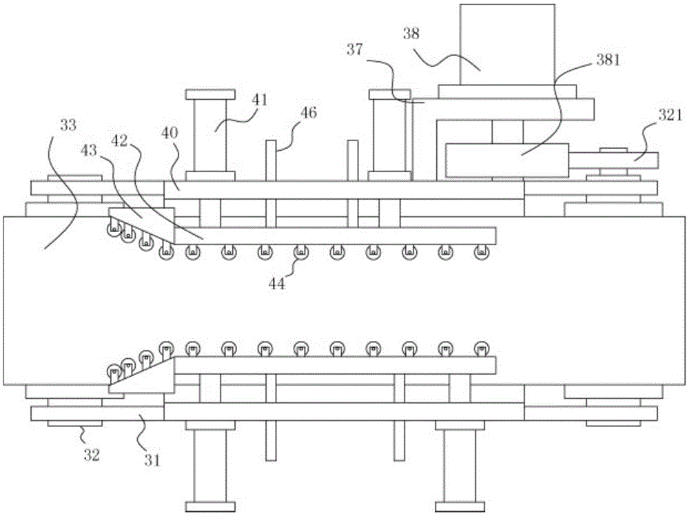
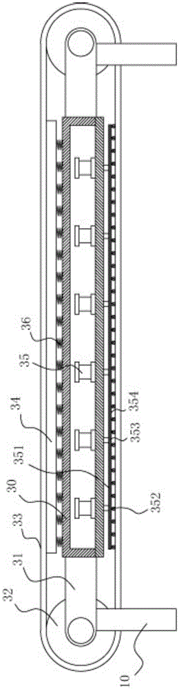
[0019] Example: see Figure 1 to Figure 3 As shown, a ceramic cutting and conveying device with automatic correction includes a frame 10, and the frame 10 includes a middle casing 30, and support plates 31 are fixed at the front and rear ends of the left and right outer walls of the middle casing 30. , the two ends of the drive roller 32 are hinged on the corresponding two support plates 31, the conveyor belt 33 is tensioned on the two drive rollers 32, and the legs are fixed on the bottom surface of the support plate 31;

[0020] The top surface of the middle casing 30 is provided with an upper support plate 34, which presses against the inner wall surface of the upper part of the conveyor belt 33, and the top front and rear sides of the middle casing 30 are also fixed with vertical plates 40. , two vertical boards 40 are located on both sides of the conveyor belt 33, a plurality of guide cylinders 41 are fixed on the vertical boards 40, and the push rods of the guide cylinde...


PUM


Abstract

The invention discloses a ceramic cutting and conveying device with an automatic correction function. The ceramic cutting and conveying device comprises a rack. The rack comprises a middle shell. Supporting plates are fixed to the front end and the rear end of the left outer side wall of the middle shell and the front end and the rear end of the right outer side wall of the middle shell. The two ends of each driving roller are hinged to the two corresponding supporting plates. A conveying belt is tensioned on the two driving rollers. Landing legs are fixed to the bottom faces of the supporting plates. An upper supporting plate is arranged on the top face of the middle shell and pressed on the inner wall face of the upper part of the conveying belt in an abutting manner. Vertical plates are further fixed to the front side and the rear side of the top face of the middle shell, the two vertical plates are located on the two sides of the conveying belt, and a plurality of guide air cylinders are fixed to the vertical plates. Push rods of the guide air cylinders penetrate the vertical plates and are fixedly provided with guide plates. The positions of the two driving rollers are fixed, and relative movement is avoided. Meanwhile, ceramic products can be moved to the middle of the conveying belt through guide wheels arranged on the guide plates and front guide plates of the ceramic cutting and conveying device, and it is guaranteed that the ceramic products are conveyed normally and safely.

Description

Technical field: [0001] The invention relates to the technical field of ceramic processing equipment, in particular to a ceramic cutting and conveying device with automatic correction. Background technique: [0002] Existing ceramic products are usually conveyed by conveyor belts. During conveying, the conveyor belt is usually tensioned by two transmission rollers, which is realized by adjusting the distance between the two transmission rollers, so that one of the two transmission rollers must be It can move laterally, so that the firmness of the two drive rollers is limited, and its effect is limited; [0003] Moreover, when ceramic products are placed on the conveyor belt, they are generally not placed in the middle, and sometimes they are placed on the edge of the conveyor belt. Especially spherical or cylindrical products are easy to fall off the conveyor belt, resulting in unqualified products and reducing the product rate. . Invention content: [0004] The purpose ...

Claims


Application Information

Patent Timeline
IPC IPC(8): B65G23/44B65G21/20
CPCB65G21/20B65G21/2045B65G23/44
Inventor 叶侃
Owner NANTONG BAOTIAN PACKING MACHINERY
Why Eureka
Try Eureka