A magnetic belt

A technology for magnetically separating belts and belts, applied in the direction of conveyor objects, rollers, transportation and packaging, etc., can solve the problems of insufficient utilization of parts, unsatisfactory tailing rate, and low installation accuracy, so as to solve the problems of magnetic packaging and Magnetic inclusions, ensuring long-term safe operation, and improving the efficiency of magnetic separation

Active Publication Date: 2018-12-07
CHENGDU LEEJUN IND
View PDF7 Cites 0 Cited by
  • Summary
  • Abstract
  • Description
  • Claims
  • Application Information

AI Technical Summary

Problems solved by technology

When it is used as a conveying device, the materials are usually accumulated on the surface of the belt, and the magnetic materials and non-magnetic materials are mixed together, so that when the magnetic separation equipment throws the tail, the magnetic materials are mixed in the non-magnetic materials before being captured by the magnetic field. Into the tailings, resulting in unsatisfactory tailings throwing rate
At the same time, during the operation of the belt, the conveyor belt often appears "deviation" due to reasons such as low processing or installation accuracy of the belt parts and uneven materials, resulting in a large amount of material spilling along the way, and even more serious equipment damage and other serious consequences; at the same time, the purpose of the idler installed under the conveyor belt is to support the belt and prevent belt wear. Therefore, the material used for the idler is often a stainless steel body (or carbon steel Q235A) plus a rubber jacket. Other functions of the roller, resulting in a single function of the idler, and the parts are not fully utilized

Method used


Image

  • A magnetic belt
  • A magnetic belt
  • A magnetic belt

Examples


Embodiment 1

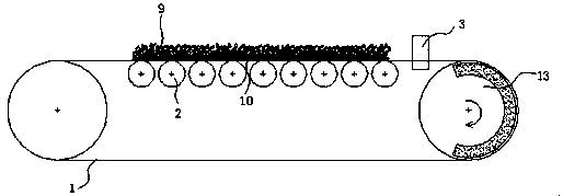
[0028] Such as figure 1 As shown, a magnetic separation belt, the inner side of the belt on the conveyor belt 1 is provided with a magnetic idler 2, and the two sides of the conveyor belt 1 are provided with a conveyor belt deviation correction wheel set 3, and the conveyor belt deviation correction wheel set 3 is installed on the elastic support 14. On the conveyor belt A magnetized wheel 13 is provided at the end of the belt in the moving direction, and the magnetic field range of the idler 2 covers the conveyor belt 1 adjacent to the idler 2 .

[0029] In the above structure, the conveyor belt deviation correcting wheels 3 arranged on both sides of the conveyor belt 1 can effectively prevent the deviation of the conveyor belt 1, eliminate the harm of "deviation", and ensure the normal operation of the conveyor belt 1. The idler 2 installed inside the conveyor belt 1, on the one hand, supports the belt and prevents the wear of the belt. On the other hand, because the idler 2...

Embodiment 2

[0037] This embodiment is the same as Embodiment 1, the difference is that the idler roller 2 is arranged on the inner side of the lower belt of the conveyor belt 1, such as Figure 5 As shown, when the material is sent to the magnetic field range of the roller 2, adjust the distance between the adjacent rollers 2, the strong magnetic material 12 is adsorbed by the roller on the lower surface of the conveyor belt 1 and falls into the concentrate mouth with the conveyor belt 1 running. , the weak magnetic material 11 is carried away by the conveying device 8 to realize the separation of the strong magnetic material 12 and the weak magnetic material 11. In order to make the roller 2 better achieve strong magnetic and weak magnetic sorting, the magnetic field strength of each roller 2 is different. In the direction of material transportation, the magnetic field strength of the roller 2 can be set alternately. , can also be gradient descent. When the magnetic material 10 enters t...


PUM


Abstract

The invention discloses a magnetic separation belt. The magnetic separation belt comprises a conveying belt, magnetic supporting rollers are arranged in the conveying belt, conveying belt correction wheel sets are arranged on the two sides of the conveying belt, a magnetization wheel is arranged at the tail end of the movement direction of an upper belt of the conveying belt, and the range of magnetic fields of the supporting rollers cover the part, adjacent to the supporting rollers, of the conveying belt. According to the magnetic separation belt, magnetic material and non-magnetic material in conveyed material can be layered on the belt, the conveying belt can be effectively prevented from deflecting and can be operated safely for a long time, and the magnetic separation efficiency of a magnetic separator can be improved.

Description

technical field [0001] The invention relates to the field of mine magnetic separation equipment, in particular to a magnetic separation belt. Background technique [0002] In existing magnetic separators, magnetic separation belts are usually used as conveying and sorting equipment. When it is used as a conveying device, the materials are usually accumulated on the surface of the belt, and the magnetic materials and non-magnetic materials are mixed together, so that when the magnetic separation equipment throws the tail, the magnetic materials are mixed in the non-magnetic materials before being captured by the magnetic field. Into the tailings, resulting in unsatisfactory tailings throwing rate. At the same time, during the operation of the belt, the conveyor belt often appears "deviation" due to reasons such as low processing or installation accuracy of the belt parts and uneven materials, resulting in a large amount of material spilling along the way, and even more serio...

Claims


Application Information

Patent Timeline
Patent Type & Authority Patents(China)
IPC IPC(8): B65G39/08B65G15/64
CPCB65G15/64B65G39/08B65G2201/04
Inventor 何亚民魏勇徐智平
Owner CHENGDU LEEJUN IND
Why Eureka
Try Eureka