

Traffic cone for urban inland inundation
A technology for urban waterlogging and traffic cones, applied in the field of traffic cones, can solve problems such as being easily washed away by water and not working
- Summary
- Abstract
- Description
- Claims
- Application Information
AI Technical Summary
Problems solved by technology
Method used
Image

Examples
Embodiment Construction
[0019] The present invention will be further described below in conjunction with accompanying drawing.
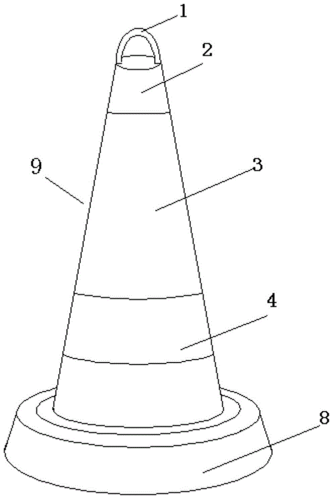
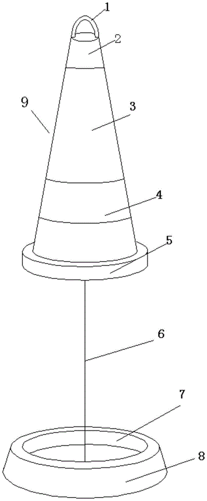
[0020] see figure 1 with figure 2 , a traffic cone for urban flooding, comprising a cone and a base, the cone is a buoy vertical cone 9, the buoy vertical cone 9 has floatability and fall resistance, the base is a counterweight base 9, and the buoy is upright A soft rope 6 is connected between the type cone body 9 and the counterweight type base 8 .
[0021] Further, a circular pull ring 1 is provided on the top of the vertical cone 9 of the buoy. The circular pull ring 1 is convenient for the transportation of traffic cones for urban waterlogging.
[0022] Further, the lower part of the side surface of the buoy vertical cone 9 is provided with a ring-shaped warning paint 4 .
[0023] Further, the upper part of the counterweight base 8 has a cavity 7 coincident with the bottom of the upright cone 9 of the buoy.
[0024] Further, the bottom of the upright cone 9 of the...
PUM
 Abstract
Description
Claims
Application Information