
Lock body with double unlocking method

A double lock-body technology, applied in non-mechanical transmission-operated locks, building locks, electric alarm locks, etc., can solve problems such as user inconvenience, lock design constraints, lock appearance, and unfavorable functions, and achieve easy installation and compact structure. Effect

Active Publication Date: 2018-01-12
边琢淳
View PDF5 Cites 0 Cited by
  • Summary
  • Abstract
  • Description
  • Claims
  • Application Information

AI Technical Summary

Problems solved by technology

[0002] At present, when the lock body on the market is actually used, the lock cylinder is usually installed on the lock body. After the lock is installed on the door, due to the different thickness of the actual door, different lengths of the lock cylinder are required, which requires When installing the lock, you must first confirm the thickness of the door and the installation position of the lock body on the door, which will cause a series of problems in procurement, installation, production, inventory, etc.
And because the installation position of the lock cylinder is fixed, it also poses a serious restriction on the design of the lock, which is very unfavorable to the appearance and function of the lock.
[0003] On the other hand, the locking and unlocking functions of the existing lock body must be realized by the cooperation of the key and the lock core, and when the key is lost or locked at home, the lock core needs to be replaced, which brings inconvenience to the user. For this problem, a lock body that can be automatically controlled is designed, even if there is no key, the lock can still be opened

Method used


Image

  • Lock body with double unlocking method
  • Lock body with double unlocking method
  • Lock body with double unlocking method

Examples


Embodiment 1

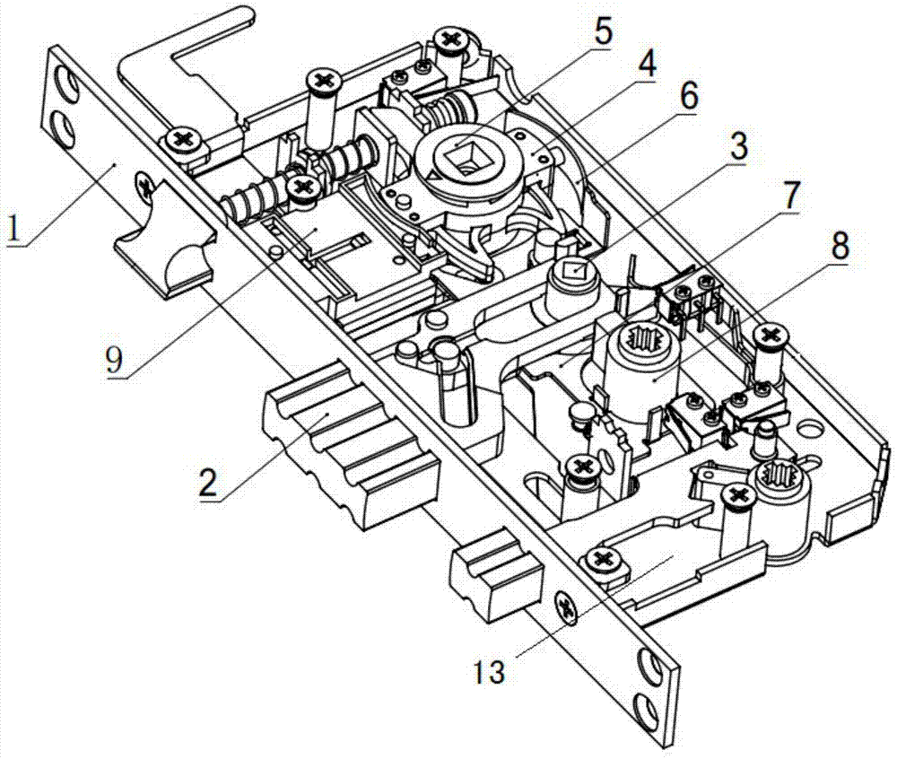
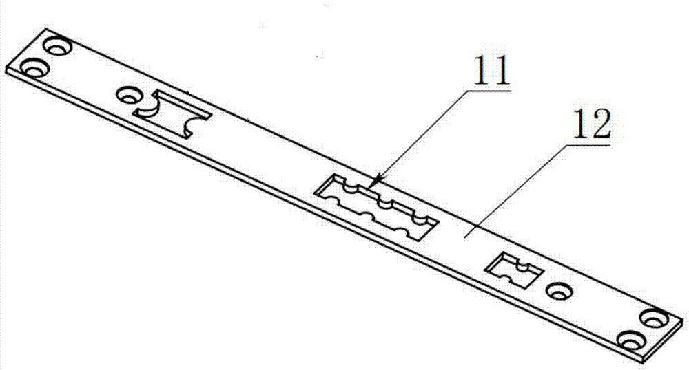
[0027] The lock body with double unlocking mode includes a housing 1. The housing 1 includes a mounting plate 13 and a bolt guide plate 12 fixed perpendicularly to the mounting plate 13. The bolt guide plate 12 is provided with a bolt guide hole 11 and the mounting plate 13 A lock tongue 2 that can telescopically slide in the lock tongue guide hole 11 is provided.

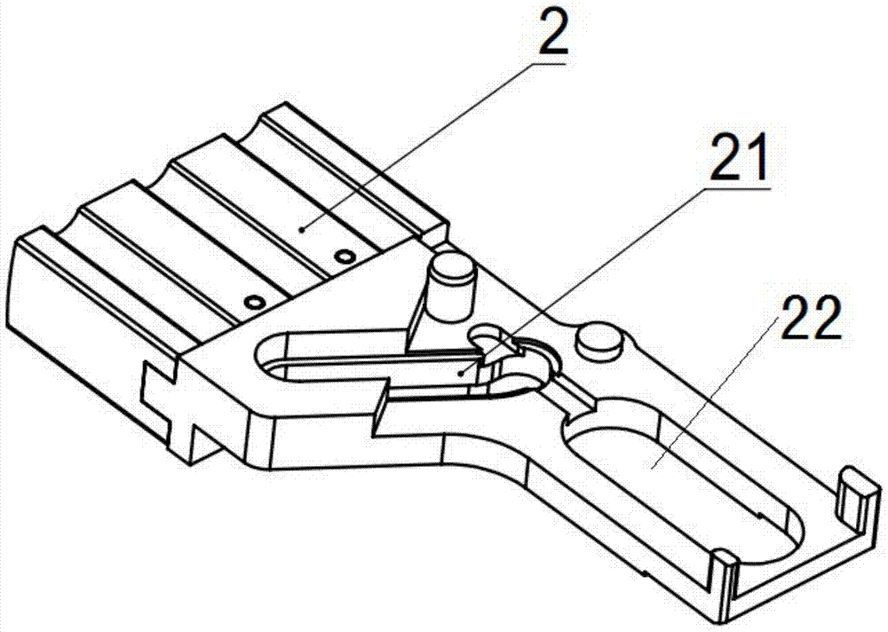
[0028] The lock body also includes a bolt shift fork 3, a manipulator assembly 4, and a handle seat 5 all fixed on the mounting plate 13. The bolt shift fork 3 is provided with a first bolt slide groove 21 and a second bolt slide Slot 22, wherein the length direction of the second bolt slide groove 22 is the same as the bolt extension direction, and the length direction of the first bolt slide groove 21 and the length direction of the second bolt slide groove 22 form an angle of 120°-135° , The latch fork 3 is provided with a first fork shaft 31, a second fork shaft 32, and a main fork shaft 33 slidably connected to t...

Embodiment 2

[0035] The same as the first embodiment, the difference is that the electronic clutch driver 9 is driven by an electromagnet to control the movement of the driving plate 91, and then unlocks or locks the entire lock.

Embodiment 3

[0037] The lock body with double unlocking mode includes a housing 1. The housing 1 includes a mounting plate 13 and a bolt guide plate 12 fixed perpendicularly to the mounting plate 13. The bolt guide plate 12 is provided with a bolt guide hole 11, and the mounting plate 13 is A lock tongue 2 that can telescopically slide in the lock tongue guide hole 11 is provided.

[0038] The lock body also includes a bolt shift fork 3, a manipulator assembly 4, and a handle seat 5 all fixed on the mounting plate 13. The bolt shift fork 3 is provided with a first bolt slide groove 21 and a second bolt slide Slot 22, wherein the length direction of the second bolt slide groove 22 is the same as the bolt extension direction, and the length direction of the first bolt slide groove 21 and the length direction of the second bolt slide groove 22 form an angle of 120°-135° , The latch fork 3 is provided with a first fork shaft 31, a second fork shaft 32, and a main fork shaft 33 slidably connected ...


PUM


Abstract

The invention relates to a lock body, in particular to a lock body with a dual unlocking manner. The lock body comprises a locking dog (2), a locking dog shifting fork (3), a controller assembly (4) and a handle seat (5). A first shifting fork shaft (31) on the locking dog shifting fork (3) is in sliding connection with a first locking dog sliding groove (21) in the locking dog (2). Engagement and disengagement grooves (51) are formed in the handle seat (5). Engagement and disengagement shafts (42) capable of reciprocating in engagement and disengagement holes (41) and stretching into the engagement and disengagement grooves (51) are arranged on the controller assembly (4). The controller assembly (4) is provided with a controller shifting fork (43) used for shifting a second shifting fork shaft (32) to rotate the locking dog shifting fork (3). Linkage between the controller assembly and the handle seat is achieved in an electric drive or mechanical drive manner, then unlocking or locking of the lock body is achieved, no lock cylinder is directly mounted on the lock body, and the advantages are brought to purchasing, mounting, production, development, inventories and the like of locks.

Description

Technical field [0001] The invention relates to a lock body, in particular to a lock body with a double unlocking mode that is compact in structure and easy to install. Background technique [0002] In the actual application of lock bodies on the market, the lock cylinder is usually installed on the lock body, so that after the lock is installed on the door, due to the actual thickness of the door, different lengths of the lock cylinder are required, which requires When installing the lock, first confirm the thickness of the door and confirm the installation position of the lock body on the door, which will cause a series of problems in procurement, installation, production, and inventory. Moreover, the fixed installation position of the lock core also poses a serious restriction on the design of the lock, which is very unfavorable to the appearance and function of the lock. [0003] On the other hand, the locking and unlocking functions of the existing lock body must be realized ...

Claims


Application Information

Patent Timeline
Patent Type & Authority Patents(China)
IPC IPC(8): E05B47/00E05B15/00E05B45/06E05B3/00E05B17/22
CPCE05B3/00E05B15/00E05B17/22E05B45/06E05B47/0001
Inventor 边琢淳
Owner 边琢淳
Learn More