
Magnet apparatus of an electrical machine with a coolant line

A technology of coolant and magnetic device, applied in cooling/ventilation devices, electromechanical devices, electrical components, etc., can solve the problem of leakage location is not simple

Inactive Publication Date: 2013-03-27
SIEMENS AG
View PDF2 Cites 2 Cited by
  • Summary
  • Abstract
  • Description
  • Claims
  • Application Information

AI Technical Summary

Problems solved by technology

[0005] Leak location is not easy when a coolant system is assembled from a large number of coolant pipe sections

Method used


Image

  • Magnet apparatus of an electrical machine with a coolant line
  • Magnet apparatus of an electrical machine with a coolant line
  • Magnet apparatus of an electrical machine with a coolant line

Examples


Embodiment Construction

[0021] The examples to be described in detail below are preferred embodiments of the present invention.

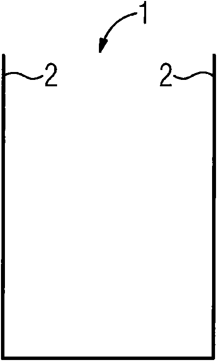
[0022] figure 1 Shown is a U-shaped first coolant pipe section 1 . It has two mutually parallel sides 2 of equal length, each of which has a free side end 2 .

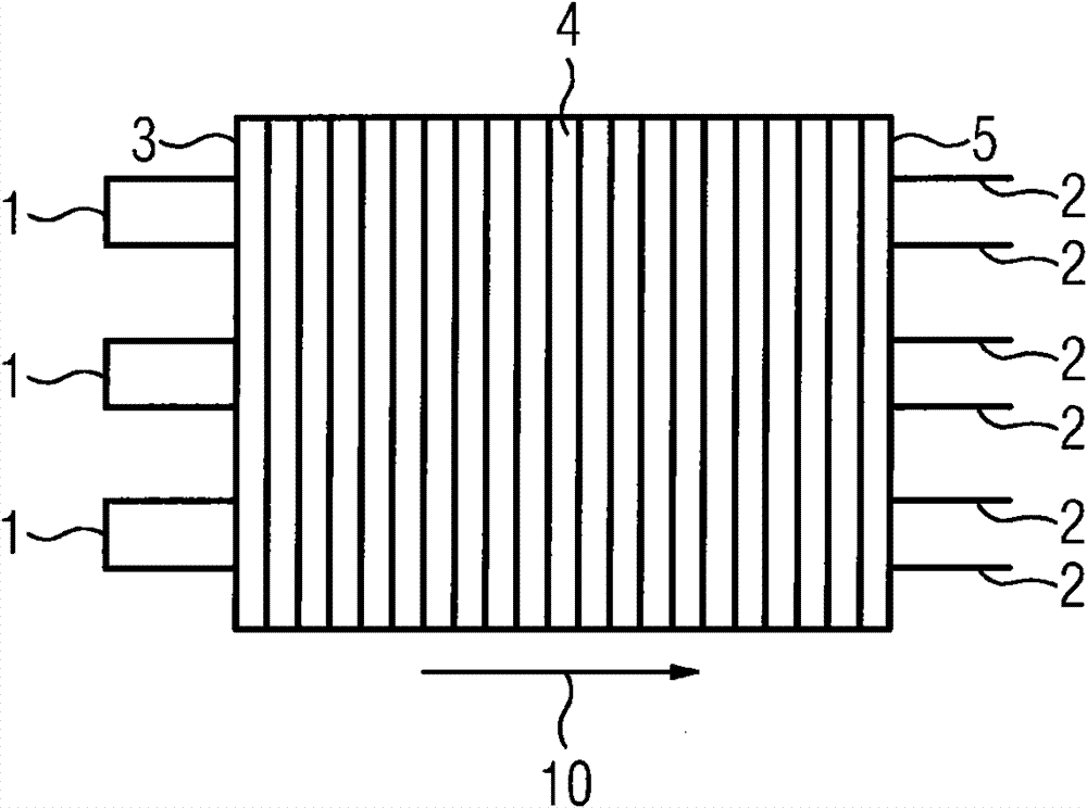
[0023] Such as figure 2 As shown, a plurality of first coolant pipe sections 1 of this type are inserted from one side 3 of the stator lamination stack 4 into corresponding bores (commonly called "channels") of the stator lamination stack 4 . The insertion direction of these first coolant pipe sections is determined by figure 2 Indicated by the arrow 10 in. The side length of any first coolant pipe section 1 is such that the side end 2 protrudes beyond the second side 5 of the stator lamination stack 4 , which is arranged opposite to the first side 3 . All the cooling passages of the ferromagnetic substrate (here designated as the sub-lamination stack 4 ) are installed with the first coolant pipe section 1 w...


PUM


Abstract

The mounting of a coolant line system in a magnet device of an electric machine is to be simplified. Therefore, a magnet device is provided, with a ferromagnetic base member (4) comprising a first (3) and an opposite second side (5) and comprising penetration holes for coolant lines from the first side (3) to the second side (5), and a plurality of first coolant line segments (1) inserted through the holes. The first coolant line segments (1) are U-shaped and each of the free leg ends (2) thereof is inserted through two of the holes of the first side (3) such that the leg ends (2) protrude from the second side (5) of the base member (4). Two of the leg ends of the first coolant line segments (1) are connected by way of a second coolant line segment. Thus, only two types of coolant line segments are needed to construct the coolant line system, and also the coolant line segments can be connected at a single side (5) of the base member (4).

Description

technical field [0001] The invention relates to a magnetic device for an electrical machine, said magnetic device comprising a ferromagnetic base body and a plurality of first coolant tube sections, said ferromagnetic base body having a first side, arranged opposite said first side A second side of the first side and a plurality of through passages (such as boreholes) for establishing a coolant pipe between the first side and the second side, and the first coolant pipe section passes through the passage. The electric machine may be an electric motor, a generator or a transformer. Background technique [0002] The coolant line system of the electric machine, in particular the coolant line system of the stator of the electric machine, optionally consists of several pipe sections. These pipe sections usually have different geometries and are connected to each other to form a closed pipe. The connection points are distributed in different parts of the magnetic device. For exa...

Claims


Application Information

Patent Timeline
Patent Type & Authority Patents(China)
IPC IPC(8): H02K1/20H02K9/19H02K15/02
CPCH02K15/02H02K1/20H02K9/19H02K9/197
Inventor 埃里希·奥尔哈默
Owner SIEMENS AG
Learn More