Nondestructive testing structure for submarine pipe in tidal range zone, processing method and testing method

A technology of non-destructive testing and processing methods, which can be applied to measuring devices, using sonic/ultrasonic/infrasonic waves to analyze solids, and using sonic/ultrasonic/infrasonic waves for material analysis, etc. High, can not completely cut off the protective tube and other problems, to achieve the effect of winding tightening, high accuracy, and ensuring transmission and reception

Inactive Publication Date: 2016-06-15
E TECH ENERGY TECH DEV CORP
View PDF6 Cites 0 Cited by
  • Summary
  • Abstract
  • Description
  • Claims
  • Application Information

AI Technical Summary

Problems solved by technology

[0002] With the development of offshore oil, the service life of sea pipes on offshore platforms is extended, and sea pipes are exposed to harsh corrosive environments such as high salt spray, humidity, and tides for a long time. The risk of corrosion of sea pipes is gradually increasing, especially when sea pipes are landed and The riser section in the tidal range area at the departure end has the worst corrosion environment. At the same time, there is a protection pipe at the landing end of the riser section (the protection pipe is the protection and support pipeline for the riser section of the sea pipe on the landing platform or off the platform, fixed on the platform jacket, and the sea pipe wears Landing on the platform through the protection pipe, completely covering the riser of the sea pipe in the tidal range area), ultrasonic guided wave detection is difficult, changes in the environment of the ultrasonic propagation medium, and the existence of the protection pipe hinder the contact between the probe and the sea pipe, and cannot be completely cut off For the protective pipe, only 1 / 2 of the circumferential pipeline can be cut off. To solve this problem, we conducted an improved test of the ultrasonic guided wave detection method

Method used


Image

  • Nondestructive testing structure for submarine pipe in tidal range zone, processing method and testing method
  • Nondestructive testing structure for submarine pipe in tidal range zone, processing method and testing method
  • Nondestructive testing structure for submarine pipe in tidal range zone, processing method and testing method

Examples


Embodiment Construction

[0028] In order to further understand the invention content, characteristics and effects of the present invention, the following examples are given, and detailed descriptions are as follows in conjunction with the accompanying drawings:

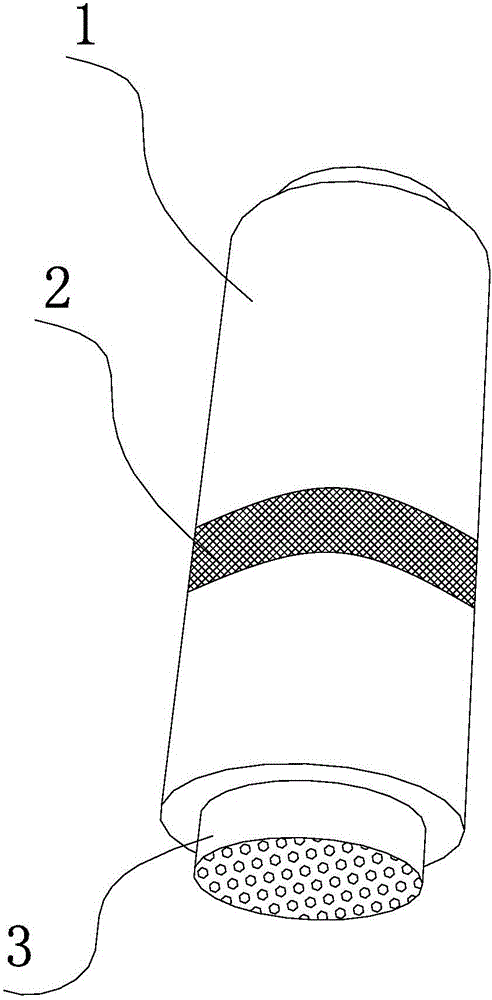
[0029] see figure 1 , a non-destructive testing structure for sea pipes in tidal range areas, comprising a sea pipe 3 with a protective pipe 1 sleeved on the outer wall; the sea pipe 3 is located at the standpipe position at the landing end or departure end; It is a magnetized magnetic sea pipe; on the protective tube 1, a gap with an axial length of a is provided; in the above-mentioned gap, an iron-cobalt belt 2 with a length a is arranged; on the outer surface of the above-mentioned iron-cobalt belt 2, Covered with epoxy resin glue; the iron-cobalt tape 2 is pasted on the outer surface of the sea pipe 3; the circumferential dimension of the gap is not less than half of the circumference of the protective pipe 1. In the preferred embodimen...


PUM


Abstract

The invention discloses a nondestructive testing structure, processing method and testing method for sea pipes in tidal range areas. The nondestructive testing structure for sea pipes in tidal range areas at least includes a sea pipe (3); the sea pipe (3) is located at the landing end Or at the position of the standpipe at the departure end; the outer wall of the sea pipe (3) is sleeved with a protection pipe (1); it is characterized in that: the sea pipe (3) and the protection pipe (1) are magnetic sea pipes after magnetization ; A gap with an axial length of a is provided on the protective tube (1); an iron-cobalt strip (2) with a length of a is arranged in the above-mentioned gap; the outer surface of the above-mentioned iron-cobalt strip (2) is coated There is epoxy resin glue; the iron-cobalt tape (2) is pasted on the outer surface of the sea pipe (3); the circumferential dimension of the gap is not less than half of the perimeter of the protective pipe (1). By adopting the above technical scheme, the present invention has the characteristics of high detection efficiency and good accuracy.

Description

technical field [0001] The invention relates to the technical field of sea pipe inspection equipment, in particular to a non-destructive inspection structure, processing method and inspection method for sea pipes in tidal range areas. Background technique [0002] With the development of offshore oil, the service life of offshore pipelines is extended, and the pipelines are exposed to harsh corrosive environments such as high salt spray, humidity, and tides for a long time. The riser section in the tidal range area at the departure end has the worst corrosion environment. At the same time, there is a protection pipe at the landing end of the riser section (the protection pipe is the protection and support pipeline for the riser section of the sea pipe on the landing platform or off the platform, fixed on the platform jacket, and the sea pipe wears Landing on the platform through the protection pipe, completely covering the riser of the sea pipe in the tidal range area), ultr...

Claims


Application Information

Patent Timeline
Patent Type & Authority Applications(China)
IPC IPC(8): G01N29/04G01N29/22
CPCG01N29/04G01N29/22G01N2291/0289G01N2291/269
Inventor 周海明张文龙
Owner E TECH ENERGY TECH DEV CORP
Why Eureka
Try Eureka