
Electrical receptacle connector

一种电连接器、插座的技术,应用在连接、两部件连接装置、连接装置的零部件等方向,能够解决无法改善上排端子与下排端子电容效应与杂讯、干扰等问题

Active Publication Date: 2016-06-15
LIANZHAN TECH ELECTRONICS KUNSHAN CO LTD
View PDF2 Cites 1 Cited by
  • Summary
  • Abstract
  • Description
  • Claims
  • Application Information

AI Technical Summary

Problems solved by technology

[0006] In view of the above problems, the present invention provides a socket electrical connector to solve the problem that the existing socket electrical connector cannot improve the capacitive effect and noise interference caused by the excessive proximity between the upper row of terminals and the lower row of terminals

Method used


Image

  • Electrical receptacle connector
  • Electrical receptacle connector
  • Electrical receptacle connector

Examples


Embodiment Construction

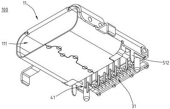
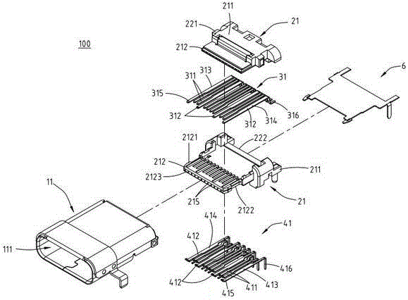
[0058] refer to figure 1 , figure 2 and image 3 , is the first embodiment of the present invention, figure 1 is a schematic diagram of the appearance, figure 2 For the decomposition diagram, image 3It is a schematic diagram of the appearance section. The socket electrical connector 100 of the present invention is a USB Type-C connection interface specification. In this embodiment, the socket electrical connector 100 includes a shielding shell 11 , an insulating body 21 , a plurality of upper row flat terminals 31 and a plurality of lower row flat terminals 41 . In addition, the electrical receptacle connector 100 further includes a grounding piece 6 , and the grounding piece 6 is disposed in the insulating body 21 and located between the upper row of flat terminals 31 and the lower row of flat terminals 41 .

[0059] please refer again figure 2 and image 3 , the shielding shell 11 is a hollow shell, and the inside of the shielding shell 11 has a receiving groove ...


PUM


Abstract

An electrical receptacle connector includes an insulated housing, upper-row receptacle terminals, and lower-row receptacle terminals. The insulated housing includes a base portion and a tongue portion extended from one side of the base portion. The tongue portion has an upper surface, a lower surface, and a front lateral surface. The lower-row receptacle terminals correspond to the upper-row receptacle terminals and include signal terminals which include high speed transmitting terminals. Each of the high speed transmitting terminals includes a bending portion, an extension portion, and a cutout portion. The bending portion is extended upward from the front end of the flat contact portion and inserted into the tongue portion, the extension portion is extended forward from the top of the bending portion toward the front lateral surface, and the cutout portion is defined at the extension portion and near to the bending portion.

Description

technical field [0001] A socket electrical connector, especially a socket electrical connector. Background technique [0002] The commonly used electrical connector interface is Universal Serial Bus (USB for short), and it is widely used by the public because of its smaller size and portability. It is common in various portable devices such as smart mobile communication devices and digital cameras. The connection hole of the electronic device and the corresponding transmission line are set and used for docking. [0003] The existing USB Type-C socket electrical connector includes an insulating body, a plurality of upper terminals and a plurality of lower terminals. The insulating body includes a base and a tongue extending from one side of the base. And each upper row of terminals is arranged on the base and the tongue plate, and each upper row of terminals is arranged on the upper surface of the tongue plate at the front part. Each lower row of terminals is formed on the...

Claims


Application Information

Patent Timeline
Patent Type & Authority Applications(China)
IPC IPC(8): H01R13/6461H01R13/6474H01R13/02
CPCH01R13/02H01R13/6461H01R13/6474H01R13/6581H01R24/60
Inventor 高雅芬蔡侑伦侯斌元廖崇甫陈茂胜
Owner LIANZHAN TECH ELECTRONICS KUNSHAN CO LTD
Learn More