Electrical contact of electrical connector

a technology of electrical connectors and electrical contacts, applied in the direction of coupling contact members, coupling device connections, electric discharge lamps, etc., can solve the problems of unwelcome deviation from the regulated 85+/15 of the contact, and achieve the effect of increasing the mutual capacitance effect and lowering the impedan

Active Publication Date: 2020-06-09
FUDING PRECISION COMPONENTS SHENZHEN +1
View PDF18 Cites 0 Cited by
  • Summary
  • Abstract
  • Description
  • Claims
  • Application Information

AI Technical Summary

Benefits of technology

[0004]An object of the invention is to provide an electrical connector with an insulative housing having opposite top and bottom faces thereof, and therein a plurality of passageways each extending through both the opposite top and bottom faces in the vertical direction. A plurality of contact are received within the corresponding passageways, respectively. Each contact has juxtaposed first body and second body perpendicular to each other via a linking section connected therebetween viewed in the vertical direction. A spring arm extends upwardly from the first body and includes a plate / base section adjacent to the first body, a narrow / curved connecting / middle section, and an enlarged bulged contacting section at a free end thereof. The arrangement of the contacts is to have the neighboring contacts closer to each other either in a front-to-back direction or a transverse direction perpendicular to the front-to-back direction during operation for increasing mutual capacitance effect to lower the impedance.

Problems solved by technology

Anyhow, some unwelcomed deviation away from the regulated 85+ / −15Ω of the contact occurs due to the positions and the dimensions of the contacting section and the tail section disadvantageously.

Method used


Image

  • Electrical contact of electrical connector
  • Electrical contact of electrical connector
  • Electrical contact of electrical connector

Examples


Embodiment Construction

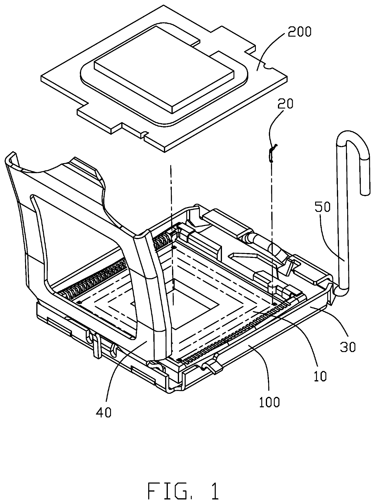
[0016]The electrical connector 100 connects the electronic package 200 to the printed circuit board 300. The connector 100 includes an insulative housing 10 with a plurality of passageways 11 extending therethrough to receive the corresponding contacts 20, respectively. The connector 100 further includes a metallic stiffener 30 surrounding the housing 10, and the load plate 40 and the lever 50 respectively pivotally mounted to two opposite ends of the stiffener 101 wherein the lever 50 is used to fasten the load plate 40 in position. Notably, the housing 10 defines a front-to-back / first direction Y and a transverse / second direction X perpendicular to each other and commonly perpendicular to the vertical direction Z. In this embodiment, the load plate 40 and the lever 50 are located at opposite ends of the stiffener 30 in the front-to-back direction. Alternately, such arrangement made along the transverse direction or even in an oblique manner with respective to those directions is f...


PUM


Abstract

A plurality of contact are received within the corresponding passageways of the insulative housing of an electrical connector, respectively. Each contact has juxtaposed first body and second body angled with each other via a linking section connected therebetween. A resilient spring arm extends upwardly from the first body, and includes a wide plate section adjacent to the first body, a bulged contacting section at a top thereof, and a narrow connecting section therebetween. The spring arm is asymmetric with regard to a centerline of the spring arm for avoiding interference with a standoff around a neighboring passageway in a neighboring row.

Description

BACKGROUND OF THE INVENTION1. Field of the Invention[0001]The present invention relates generally to an electrical contact, and more particularly to the electrical contact with structures meeting impedance requirements. This application relates to two other copending applications with Ser. Nos. 16 / 355,857 and 16 / 357,283 both filed Mar. 18, 2019.2. Description of Related Arts[0002]U.S. Pat. No. 8,454,373 discloses en electrical contact of an electrical connector for use with a CPU (Central Processing Unit). The contact includes two juxtaposed and mutually angled parts, of which one has the resilient upwardly extending contacting section and the other has the stiff downwardly extending tail section. The feature of such patent is to provide the barbed structure on two lateral outer sides of the these two parts, respectively, for enhancing the retention force thereof compared with the earlier prior art having the barbed structure only on the part having the tail section. Anyhow, some un...

Claims


Application Information

Patent Timeline
Patent Type & Authority Patents(United States)
IPC IPC(8): H01R24/00H01R13/24H01R33/74H01R13/50H01R13/646H01R12/71
CPCH01R13/50H01R33/74H01R13/2442H01R13/646H01R12/716H01R12/714H01R13/2414H01R13/6476H01R2201/20
Inventor CHENG, SHAN-YONGHWANG, TZU-YAO
Owner FUDING PRECISION COMPONENTS SHENZHEN
Why Eureka
Try Eureka