
Key and lock

A key and coding technology, applied in the field of keys and locks, can solve the problem of increasing the number of key control combinations

Active Publication Date: 2016-06-15
URBANALPS
View PDF6 Cites 3 Cited by
  • Summary
  • Abstract
  • Description
  • Claims
  • Application Information

AI Technical Summary

Problems solved by technology

This factor significantly increases the number of available key control combinations

Method used


Image

  • Key and lock
  • Key and lock
  • Key and lock

Examples


Embodiment Construction

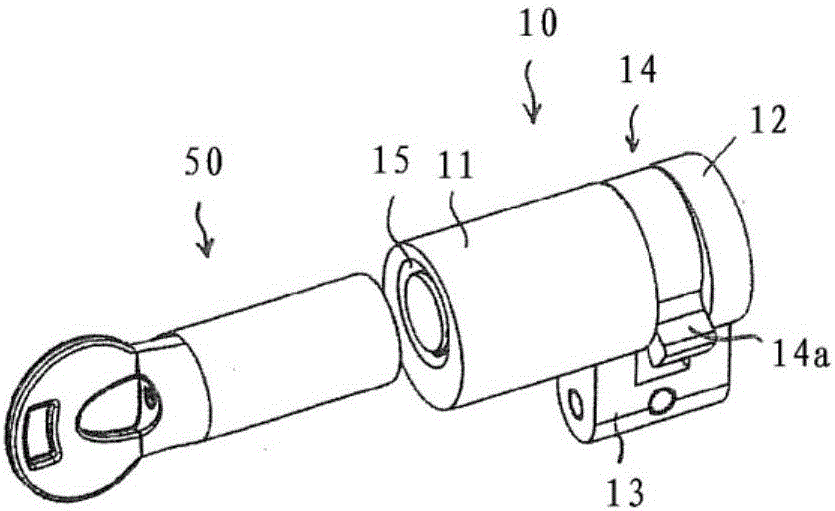
[0108] figure 1 A lock 10 and a key 50 are shown. The lock 10 comprises a housing 11 enclosing a verification device for verifying the key 50, an end plate 12 connected to the housing 11 via a bridge element 13, and a drive element 14 with a cam 14a, The drive element 14 is arranged in the space between the housing 11 and the end plate 12 . If the correct key 50 is inserted, the drive element 14 can be rotated to unlock or lock the actual locking mechanism, eg a deadbolt of a door or the like.

[0109] The lock 10 is designed such that a key 50 having a hollow geometry can be inserted. For this purpose, the lock 10 has a key cavity 15 which surrounds the authentication device. The key chamber 15 is annular in shape so as to receive a key that is formed with a coded chamber (for example, see Figure 11 Part of the coding chamber 55).

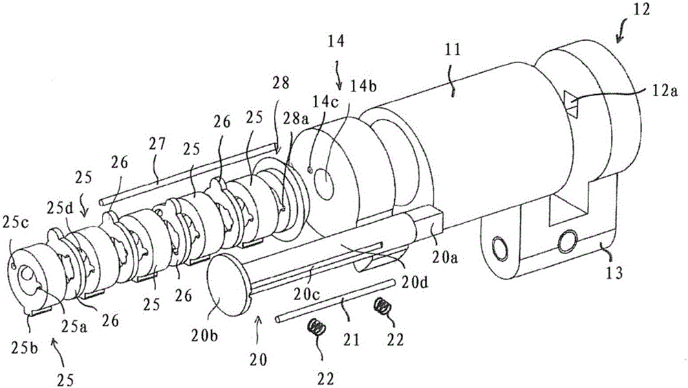
[0110] figure 2 Various components of lock 10 are shown. The lock 10 comprises a stator 20 which, in the assembled state, extends throug...


PUM


Abstract

The key comprises at least one coding cavity (55) defining a hollow geometry for coding the key. The geometry includes at least one internal undercut (60a, 60b). The lock for validating a key comprises blocking means (21, 22) coupled to a driving part (14) and validating means (25, 26) which are coupled to the blocking means so as to change the state of the blocking means when the key used with the lock has a correct coding. The validating means (25, 26) protrude at least partially into the key cavity of the lock in order to introduce the validating means at least partially into the coding cavity (55) of the key and to sense the inner face of the coding cavity.

Description

technical field [0001] This disclosure relates to keys and locks. Background technique [0002] Over the past two or three decades, many important technical improvements in the field of cylinder locks have been introduced to the market. These technical improvements have had the aim of increasing, inter alia, the number of lock combinations and / or the complexity of key duplication. [0003] Generally, improvements in increasing the number of key control combinations have been obtained by: [0004] - Increased number of tumbler pins and holes. [0005] - Production of keys with very complex shapes or variations in key contour and corresponding keyholes in the lock cylinder. [0006] - Change the shape of tumbler pins and drivers. [0007] These improvements also made lockpicking techniques—including the impression method used to produce counterfeit keys—more difficult. [0008] Cylinder locks have also been constructed to complicate key imitation. This improvement primar...

Claims


Application Information

Patent Timeline
Patent Type & Authority Applications(China)
IPC IPC(8): E05B19/00E05B29/00E05B29/10E05B47/00E05B49/00
CPCE05B29/0013E05B47/0045E05B49/006E05B19/0047E05B19/0058E05B29/0066E05B19/0023E05B19/0041
Inventor 亚历杭德罗·奥赫达冈萨雷斯-波萨达费利克斯·迈克尔·赖纳特
Owner URBANALPS
Learn More