Atomizer with mixed flue gas function

An atomizer and functional technology, applied in the field of electronic cigarettes, can solve the problems of insufficient fullness and limited length of electronic smoke, and achieve the effects of improving the overall sensory quality, making up for the lack of fullness, and overcoming the lack of fullness

Inactive Publication Date: 2016-06-22
CHINA TOBACCO YUNNAN IND
View PDF7 Cites 3 Cited by
  • Summary
  • Abstract
  • Description
  • Claims
  • Application Information

AI Technical Summary

Problems solved by technology

Different from the continuous burning of traditional cigarettes, the atomizer with the function of mixing smoke will heat up for a corresponding length of time during each puffing process of the smoker. The heating process is a From relatively low temperature to high temperature, and back to relatively low temperature process, in this process, the e-liquid with multiple components will have different temperatures due to the heating element working at different times, so as to draw different stages of the same puff of smoke, Different components and fragrance substances are evaporated, so the evaporated smoke enters an air duct at the end of the existing atomizer for collecting atomized gas, with a limited length and a diameter of only 0.3-3mm. When passing through the air duct, it cannot be well mixed evenly before entering the mouth of the smoker, and the particle size of the smoke from the electronic cigarette is only about one-tenth of the particle size of the smoke formed after the traditional cigarette is burned. Patients often have a feeling of insufficient plumpness of electronic cigarette vaporized smoke after oral cavity

Method used


Image

  • Atomizer with mixed flue gas function
  • Atomizer with mixed flue gas function
  • Atomizer with mixed flue gas function

Examples


Embodiment 1

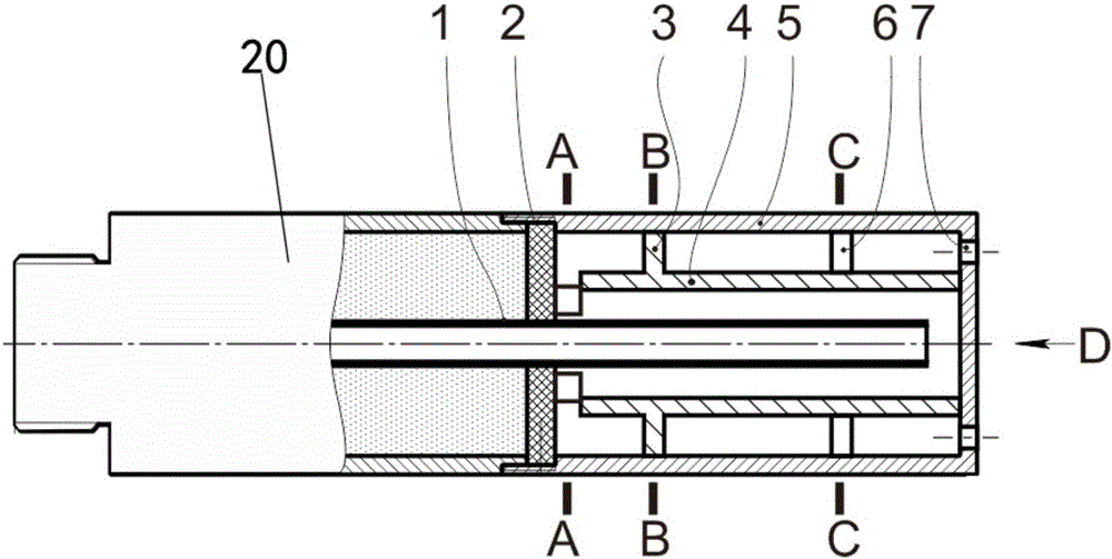
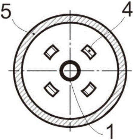
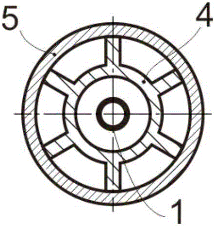
[0042] Figure 1-5 The atomizer shown with the function of mixing smoke includes an atomizer main body 20 and an air guide tube 1 which is arranged in the atomizer main body 20 and has one end protruding from the tail end 2 of the atomizer main body. The air guide tube 1 can also be Insert from the end 2 of the atomizer body;

[0043] It also includes a shell 5 installed on the tail end 2 of the atomizer body and the other end is closed, and an inner tube which is sleeved in the shell 5 and has one end in contact with the tail end 2 of the atomizer body and the other end in airtight contact with the closed end of the shell 5 4;

[0044] The air duct 1 extends to the closed end of the shell 5 and is spaced at a certain distance;

[0045] A first air flow channel is formed between the air guide tube 1 and the inner tube 4;

[0046] A second airflow channel is formed between the inner tube 4 and the outer shell 5;

[0047] The outer wall of the inner tube 4 is provided with t...

Embodiment 2

[0055]As a further improvement of Embodiment 1, such as Figure 6-10 As shown, wherein, the end of the inner tube 4 facing the atomizer main body 20 is provided with a connecting ring 8 detachably connected thereto, and the air guide hole is provided on the connecting ring 8 .

[0056] Further, the end of the inner tube 4 facing the closed end of the outer casing 5 is provided with an isolating ring 9 detachably connected thereto; the isolating ring 9 is provided with a radial spacer 10 to isolate its two sides, which is separated from the closed end of the outer casing 5 A mixing chamber is formed between them, and a ventilation hole communicating with the mixing chamber and the second air flow channel is provided on the spacer ring 9; the air outlet 7 is provided on the closed end of the shell 5 and can communicate with the mixing chamber and the outside world. The rest are basically the same as in Embodiment 1. Of course, only the connection ring 8 or the spacer ring 9 is ...

Embodiment 3

[0059] As a further improvement of Embodiment 2, such as Figure 11-15 As shown, wherein, the air guide tube 1 is covered with a plurality of annular plates 11 spaced a certain distance from the inner wall of the inner tube 4, and the rest of the structure is basically the same as that of the second embodiment. The annular plate 11 can further block the passing flue gas to form eddies and turbulent flows, further increasing the mixing speed of the flue gas.

[0060] In this embodiment, the air guide tube 1 is provided with a ring plate 11 on the entire outer wall of the shell 5. Obviously, only a small amount of ring plates 11 can be placed on the air guide tube 1; One or several ring plates 11 near the air outlet end are fixedly connected with the air duct 1, such as interference fit, bonding or heat bonding without residual odor, so as to ensure that each ring plate 11 will not be damaged during use, transportation, etc. Or the carrying state is separated from the air guide...


PUM


Abstract

The invention discloses an atomizer with a mixed flue gas function, and aims to provide the atomizer having the mixed flue gas function and capable of realizing better smoking mouth feel. The atomizer comprises an atomizer main body and a gas guide pipe, and further comprises a housing and an inner pipe, wherein the gas guide pipe is arranged in the atomizer main body and one end of the gas guide pipe extends out of the tail end of the atomizer main body; the housing is mounted at the tail end of the atomizer main body and the other end of the housing is closed; the inner pipe is mounted in the housing in a sleeving manner and one end of the inner pipe is in contact with the tail end of the atomizer main body while the other end of the inner pipe is in sealed contact with the closed end of the housing; the gas guide pipe extends to the closed end of the housing and is spaced from the housing for a certain distance; a first gas flow channel is formed between the gas guide pipe and the inner pipe; a second gas flow channel is formed between the inner pipe and the housing; at least two groups of bumps in contact with the inner wall of the housing are arranged on the outer wall of the inner pipe; a gas guide hole for communicating the first gas flow channel with the second gas flow channel is formed in one end, facing to the atomizer main body, of the inner pipe; and at least one gas outlet for communicating the second gas flow channel with the outside is formed in the closed end of the housing.

Description

technical field [0001] The invention relates to the technical field of electronic cigarettes, in particular to an atomizer with the function of mixing smoke. Background technique [0002] The existing atomizer with the function of mixing smoke is soaked in the electronic cigarette liquid by the heating element. When the atomizer is connected correctly and reliably with the electronic cigarette rod with battery, it only needs to be sucked or connected to the power supply, and the atomizer The middle heating element is turned on, and the heating element starts to heat the e-cigarette liquid. Different from the continuous burning of traditional cigarettes, the atomizer with the function of mixing smoke will heat up for a corresponding length of time during each puffing process of the smoker. This heating process is a From relatively low temperature to high temperature, and back to relatively low temperature process, in this process, the e-liquid with multiple components will h...

Claims


Application Information

Patent Timeline
Patent Type & Authority Applications(China)
IPC IPC(8): A24F47/00
CPCA24F47/008
Inventor 吴俊朱东来李廷华陈永宽汤建国韩熠洪鎏李寿波张霞巩效伟
Owner CHINA TOBACCO YUNNAN IND
Why Eureka
Try Eureka