Aerosol Guiding Device And Aerosol Generating System Comprising Said Aerosol Guiding Device

a technology of aerosol generating system and guiding device, which is applied in the direction of electric/magnetic/electromagnetic heating, lighting and heating apparatus, tobacco, etc., and can solve the problems of significant inconsistencies in pressure drop achieved, lack of flexibility of the entire system, and subsequent variance in the resultant air flow within the aerosol generating system

Active Publication Date: 2019-10-17
JT INT SA
View PDF3 Cites 2 Cited by
  • Summary
  • Abstract
  • Description
  • Claims
  • Application Information

AI Technical Summary

Benefits of technology

[0008]The present invention seeks to provide an aerosol generating system such as an electronic cigarette which overcomes the abovementioned problems, including providing flexible and improved means for modifying and regulating air flow within the aerosol generating system.
[0009]The present inventors have recognized that a greater degree of flexibility and control is required to enhance the smoking experience of an aerosol generating system such as an electronic cigarette.

Problems solved by technology

A problem with known devices that attempt to control air flow speed, however, is that inconsistencies within the system, for example due to manufacturing tolerances, or inconsistencies due to external factors, for example varied suction of a user, may lead to a consequent variance in the resultant air flow within the aerosol generating system.
In addition, there are often significant inconsistencies in the pressure drop achieved in vaporisation chambers used across electronic cigarettes of the same model.
A further problem is that if these inconsistences arise in a particular design of electronic cigarette, it is almost impossible to then change that design in order to further modify air flow, thus resulting in lack a flexibility of the entire system.
Due to the inconsistency in pressure drop within current aerosol generating systems, it is possible that no liquid or solid material to be vaporised may be present on the wick when a user provides suction action on the mouthpiece.
This leads to an unpleasant effect called “dry puffing” where the capillary wick is burnt by the heater and a burnt taste is experienced by the user.
In other cases, too much liquid or solid material may be present on the capillary wick, in which case the heater cannot vaporise all of said material, thus resulting in an inefficient system.

Method used


Image

  • Aerosol Guiding Device And Aerosol Generating System Comprising Said Aerosol Guiding Device
  • Aerosol Guiding Device And Aerosol Generating System Comprising Said Aerosol Guiding Device
  • Aerosol Guiding Device And Aerosol Generating System Comprising Said Aerosol Guiding Device

Examples


Embodiment Construction

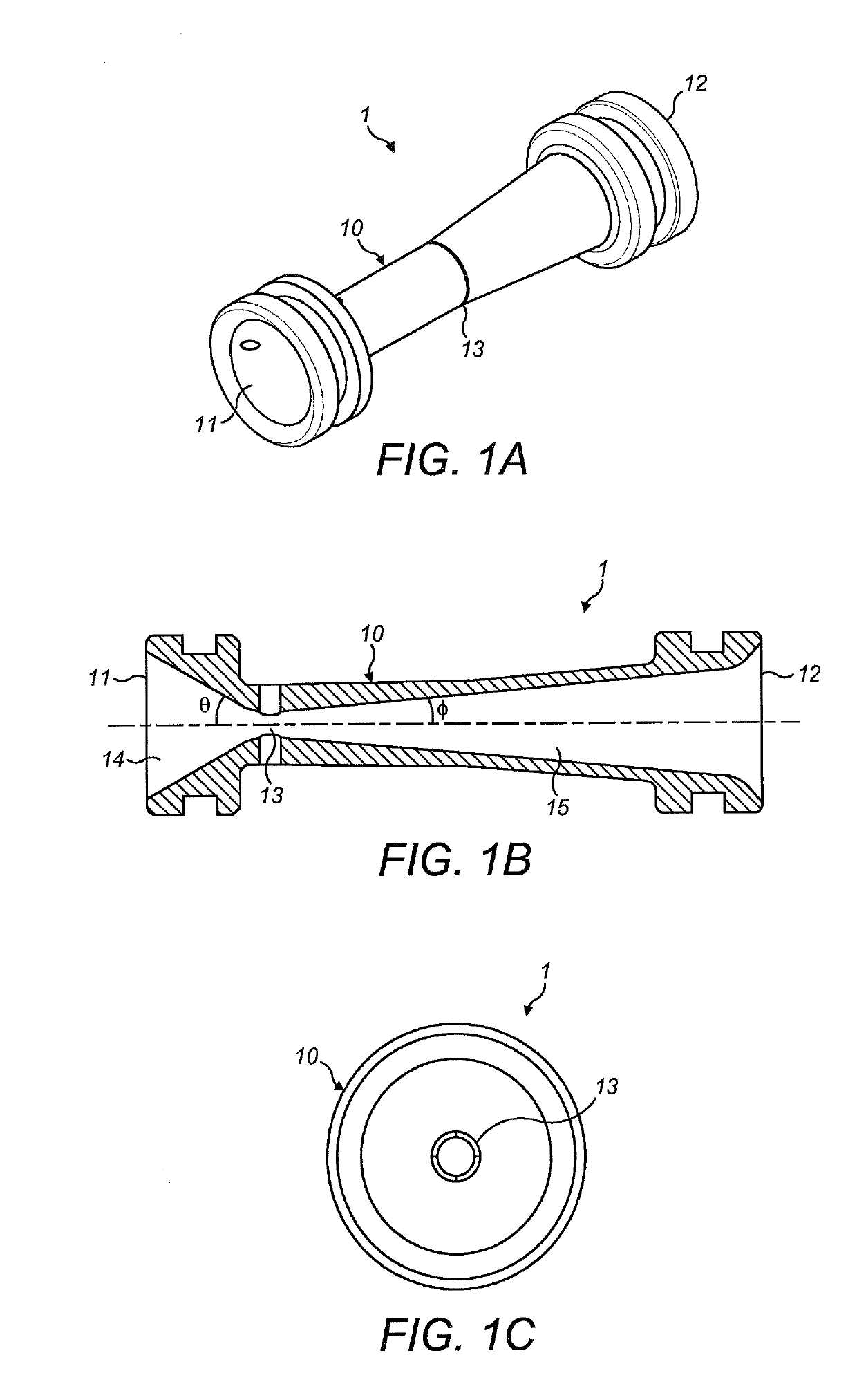
[0065]FIG. 1 shows an example of an aerosol guiding device 1 according to the present invention. FIG. 1A shows a schematic view of such an aerosol guiding device 1, FIG. 1B shows a side view of the aerosol guiding device 1 and FIG. 1C shows an end view of the aerosol guiding device 1. In each of FIGS. 1A to 1C, it can be seen that the aerosol guiding device 1 comprises air inlet 11 and air outlet 12 of chamber 10. Aerosol delivery means of an aerosol generating system can be configured such that aerosol is introduced from aerosol generating means of the aerosol generating system into the chamber 10 in use, and an air flow route is defined from the air inlet 11 to the air outlet 12 so as to convey the aerosol to the air outlet 12.

[0066]It will be appreciated that any narrative directed to the dimensions of the chamber of the aerosol guiding device in the examples of any of the Figures, for example, the “narrowest part”, the “constricted section”, the “cross sectional area”, the dimen...


PUM


Abstract

There is provided an aerosol generating system, the system comprising: aerosol generating means; aerosol delivery means; and an aerosol guiding device. The aerosol guiding device comprises a chamber having an air inlet and an air outlet and the aerosol delivery means is configured such that aerosol is introduced from the aerosol generating means into the chamber in use. An airflow route is defined from the air inlet to the air outlet so as to convey the aerosol to the air outlet, and the relative dimensions of the air inlet and the air outlet are selected to provide pressure control means for controlling the pressure differential between the air inlet and the air outlet. There is also provided an aerosol guiding device for use in an aerosol generating system, the device comprising: a chamber having an air inlet and an air outlet.

Description

CROSS-REFERENCE TO RELATED APPLICATIONS[0001]This application is a continuation of U.S. application Ser. No. 15 / 548,677, filed on Aug. 3, 2017, which is a national phase entry under 35 U.S.C. § 371 of International Application No. PCT / EP2016 / 052505, filed on Feb. 5, 2016, published in English, which claims priority from United Kingdom Application No. 1501951.6, filed Feb. 5, 2015, the disclosures of all of which are hereby incorporated herein by reference.BACKGROUND OF THE INVENTION[0002]The present invention relates to an aerosol guiding device and an aerosol generating system containing said aerosol guiding device. More particularly, it relates to an aerosol guiding device for controlling and modifying air flow for use in an aerosol generating system such as an electronic cigarette.[0003]Aerosol generating systems such as electronic cigarettes are becoming well known in the art. The operating principle for these electronic cigarettes usually centres around providing a flavoured va...

Claims


Application Information

Patent Timeline
Patent Type & Authority Applications(United States)
IPC IPC(8): A24F47/00A61M11/04A61M11/06A61M15/06F22B1/28A61M11/00H05B6/10A24F40/10A24F40/485
CPCA24F47/008A61M11/04A61M2205/3653A61M2205/8206A61M2207/00A61M11/042A61M15/06A61M2205/8212A61M11/06A61M11/005A61M2206/20A61M11/001A61M2206/14A61M2205/3331F22B1/28H05B6/108A61M2205/3633A61M2205/127A24F40/10A24F40/40A24F40/465A24F40/42A24F40/50A24B15/167A24F40/44H05B3/06H05B3/44H05B2203/014H05B2203/021H05B2203/022A24F47/00A24F40/485
Inventor ROGAN, ANDREW ROBERT JOHN
Owner JT INT SA
Why Eureka
Try Eureka