Antitheft zipper

A zipper and chain technology, applied in the field of zippers, can solve problems such as insufficient zipper strength, and achieve the effect of increasing difficulty

Inactive Publication Date: 2016-06-22
郑景文
3 Cites 0 Cited by

AI-Extracted Technical Summary

Problems solved by technology

[0002] At present, the zippers used in suitcases or luggage bags are not strong enough. In the process of use, criminals can use a sharp tool to insert the zipp...

Method used

In order to reduce the resistance that upper steel coil band 16 and lower steel coil band 18 move, upper guide wheel 34 is hinged with upper shell 15 or lower shell 17, and lower guide wheel 35 is hinged with lower chain plate 33; Last steel coil band 12 When the upper steel tape measure 3 is pulled out, the upper steel coil belt 16 presses the upper guide wheel 34, and the upper steel coil belt 16 drives the upper guide wheel 34 to rotate, reducing the friction between the upper steel coil belt 16 and the upper guide wheel 34; The steel coil belt 18 pushes down the lower guide wheel 35, and the lower steel coil belt 18 drives the lower guide wheel 35 to rotate, reducing the friction between the lower steel coil belt 18 and the lower guide wheel 35; , the upper steel coil belt 16 pushes down the upper guide wheel 34, and the upper steel coil belt 16 drives the upper guide wheel 34 to rotate, reducing the friction between the upper steel coil belt 16 and the upper guide wheel 34; the lower steel coil belt 18 presses the lower guide wheel 35, the lower steel coil belt 18 drives the lower guide wheel 35 to rotate, reducing the frictional force between the lower steel coil belt 18 and the lower guide wheel 35.
The structural representation of antitheft slide fastener shown in Fig. 1 and the right view of Fig. 1 shown in Fig. 2, antitheft slide fastener includes chain seat 1, chain 2, last steel tape measure 3 and following steel tape measure 4, chain seat 1 and Chain 2, upper steel tape measure 3 and lower steel tape measure 4 are connected; chain base 1 is provided with left upper chain groove 5, right upper chain gro...

Abstract

An antitheft zipper comprises a zipper base, a zipper strip, upper steel tape and lower steel tape. The zipper base is provided with an upper left zipper groove, an upper right zipper groove, a lower left zipper groove and a lower right zipper groove. The zipper strip comprises an upper left zipper strip, an upper right zipper strip, a lower left zipper strip, a lower right zipper strip, a zipper head sealing piece and a zipper tail sealing piece. The upper steel tape comprises an upper shell and an upper steel tape body. The lower steel tape comprises a lower shell and a lower steel tape body. The upper head end of the upper steel tape body and the lower head end of the lower steel tape body are connected with the zipper head sealing piece of the zipper strip. The upper steel tape body is connected with an upper left zipper buckle and an upper right zipper buckle. The lower steel tape body is connected with a lower left zipper buckle and a lower right zipper buckle. The antitheft zipper is installed on a luggage case or a luggage bag when used, the upper steel tape body and the lower steel tape body are arranged on the antitheft zipper, the zipper strip is sealed through the upper steel tape body of the upper steel tape and the lower steel tape body of the lower steel tape, and a criminal has higher difficulty in inserting a sharp device in the zipper to open the zipper.

Application Domain

Slide fasteners

Technology Topic

Engineering

Image

  • Antitheft zipper
  • Antitheft zipper

Examples

  • Experimental program(1)

Example Embodiment

[0009] Below in conjunction with accompanying drawing, the present invention is further described:
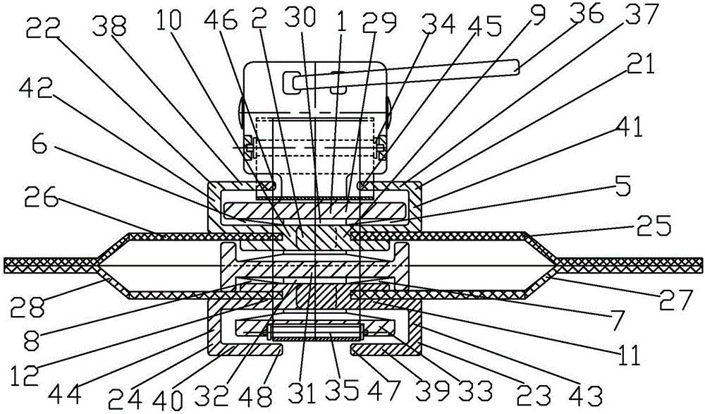
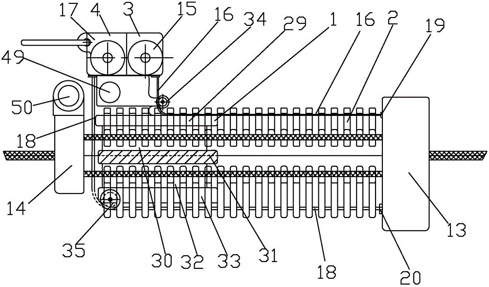
[0010] figure 1 The structural schematic diagram of the shown anti-theft zipper and figure 2 shown figure 1 The right side view of the anti-theft zipper includes chain base 1, chain 2, upper steel tape 3 and lower steel tape 4, chain base 1 is connected with chain 2, upper steel tape 3 and lower steel tape 4; chain base 1 has an upper left Chain groove 5, right upper chain groove 6, left lower chain groove 7 and right lower chain groove 8, chain 2 includes left upper chain 9, right upper chain 10, left lower chain 11, right lower chain 12, chain head seal 13 and chain tail seal Part 14; upper left chain 9, upper right chain 10, lower left chain 11 and lower right chain 12 are connected with chain head sealer 13 and chain tail sealer 14, upper left chain 9 is connected with upper right chain 10, lower left chain 11 is connected with lower right chain 12 Connection; left upper chain 9 is connected with left upper chain groove 5, right upper chain 10 is connected with right upper chain groove 6, left lower chain 11 is connected with left lower chain groove 7, right lower chain 12 is connected with right lower chain groove 8; upper steel tape measure 3 includes Upper shell 15 and last steel coil band 16, lower steel tape measure 4 comprises lower shell 17 and lower steel coil band 18, the upper head end 19 of last steel coil band 16 and the lower head end 20 of lower steel coil band 18 and the chain of chain 2 Head sealing part 13 is connected; Left upper chain 9 is provided with left upper chain buckle 21, and right upper chain 10 is provided with right upper chain buckle 22, and left lower chain 11 is provided with left lower chain buckle 23, and right lower chain 12 is provided with right lower chain buckle 24; The coil belt 16 is connected with the upper left chain buckle 21 and the upper right chain buckle 22 in a moving fit, and the lower steel coil belt 18 is connected with the lower left chain buckle 23 and the lower right chain buckle 24; Chain 2 increases the difficulty of criminals inserting chain 2.
[0011] Utilize upper steel coil band 16 and lower steel coil band 18 to seal chain 2 in order to implement, left upper chain 9 is formed by connecting a plurality of left upper chain buckles 21 with left upper chain cloth 25, and right upper chain 10 is formed with a plurality of right upper chain buckles 22 and right upper chain. Cloth 26 is connected; the upper left chain link 21 is engaged with the upper right chain link 22; It is formed by connecting with the lower left chain cloth 27, and the lower right chain 12 is formed by connecting a plurality of lower right chain buckles 24 with the lower right chain cloth 28; Cloth 28 is connected with chain head sealer 13 and chain tail sealer 14; Left upper chain cloth 25 is connected with left lower chain cloth 27, and right upper chain cloth 26 is connected with right lower chain cloth 28; Chain base 1 includes upper chain plate 29, upper closing Chain pillar 30, middle chain plate 31, lower chain pillar 32 and lower chain plate 33, upper chain plate 29 is connected with upper chain pillar 31, upper chain pillar 31 is connected with middle chain plate 31, middle chain plate 31 is connected with lower chain The closing chain column 32 is connected, and the lower closing link column 32 is connected with the lower link plate 33; or, the upper link plate 29, the upper closing link column 30, the middle link plate 31, the lower closing link column 32 and the lower link plate 33 are made of an integrated material The upper shell 15 is provided with an upper guide wheel 34, the upper steel coil belt 16 is connected with the chain head sealing member 13 through the upper guide wheel 34, and the upper shell 15 is connected with the upper chain plate 29; the lower chain plate 33 is provided with a lower guide wheel 35 , the lower steel coil belt 18 is connected with the chain head sealing member 13 through the lower guide wheel 35, the lower casing 17 is connected with the upper casing 15, and the upper casing 15 or the lower casing 17 is provided with a handle 36; the upper left chain groove 5 is composed of an upper chain plate 29 and The middle link plate 31 is formed by the left side of the upper chain column 30, and the left upper chain slot 5 is located on the left side of the upper chain column 30; the right upper chain slot 6 is formed by the upper link plate 29, the middle link plate 31 and the right side of the upper chain column 30 , the right upper chain slot 6 is located on the right side of the upper chain column 30; the left lower chain slot 7 is formed by the middle link plate 31, the lower link plate 33 and the left side of the lower link column 32, and the left lower chain slot 7 is located on the left side of the lower link column 32 The lower right chain groove 8 is formed by the middle chain plate 31 and the lower chain plate 33 and the right side of the lower chain column 32, and the right lower chain groove 8 is located on the right side of the lower chain column 32.
[0012] The using method of anti-theft zipper is: when using, the upper left chain cloth 25, the lower left chain cloth 27, the upper right chain cloth 26 and the lower right chain cloth 28 are connected with the mouth of the suitcase or the pocket of the luggage bag, and the handle 36 is positioned at Outside the luggage case or luggage bag; when the luggage case or luggage bag is closed, the handle 36 pulls the upper shell 15 or the lower shell 17 and the chain seat 1 to move, and the chain seat 1 moves with the handle 36, using the upper left chain groove of the chain seat 1 5 and the upper right chain groove 6 make the upper left chain 9 and the upper right chain 10 bite together; and utilize the lower left chain groove 7 and the lower right chain groove 8 of the chain seat 1 to make the lower left chain 11 and the lower right chain 12 bite together; put the luggage case At the same time, the upper steel tape 3 moves with the handle 36, and the upper steel tape 16 is pulled out as the upper steel tape 3 moves, and the pulled out upper steel tape 16 is locked by the left upper chain buckle 21 and the upper right chain buckle 22 are buckled on the upper chain plate 29; at the same time, the lower steel tape 4 moves with the handle 36, and the lower steel tape 18 is pulled out following the movement of the lower steel tape 4, and the pulled out lower steel tape 18 Buckle below the lower chain plate 33 by the lower left chain buckle 23 and the lower right chain buckle 24; Utilize the upper steel coil band 16 and the lower steel coil band 18 to seal the upper left chain 9 and the upper right chain 10 and the lower left chain 11 and the lower right chain 12 The occlusal opening increases the difficulty for criminals to use a sharp tool to insert the zipper; when opening the mouth of the suitcase or the pocket of the luggage bag, the chain seat 1 is pulled by the handle 36 to move in the opposite direction with the hand, and the chain seat 1 moves with the handle 36. The chain base 1 separates the engaged upper left chain 9 from the upper right chain 10, and separates the engaged lower left chain 11 from the lower right chain 12; at the same time, the upper steel tape measure 3 moves in the opposite direction with the handle 36, and the upper steel coil belt 16 moves in the upper steel The tape measure 3 is retracted in the upper steel tape measure 3 under the elastic force of the torsion spring of the tape measure 3;
[0013] When the anti-theft zipper closes the suitcase or luggage bag, the handle 36 pulls the chain seat 1 to move, the upper left chain 9 is introduced by the upper left chain slot 5 of the chain seat 1, and the upper right chain 10 is introduced by the upper right chain slot 6 of the chain seat 1. The left upper chain groove 5 and the right upper chain groove 6 of the seat 1 move to make the left upper chain buckle 21 and the right upper chain buckle 22 snap connected; The lower chain buckle 24 is engaged and connected; at the same time, the upper steel tape 3 moves with the handle 36, and the upper steel coil belt 16 is pulled out along with the movement of the upper steel tape 3. The hook 37 and the upper right horizontal hook 38 of the upper right chain buckle 22 are buckled on the upper chain plate 29; and the lower steel tape measure 4 moves with the handle 36, and the lower steel coil belt 18 is pulled out along with the lower steel tape measure 4. The lower steel coil belt 18 is fastened below the lower chain plate 33 by the lower left horizontal hook 39 of the lower left chain buckle 23 and the lower right horizontal hook 40 of the lower right chain buckle 24 .
[0014] In order to implement the upper steel coil band 16 and the lower steel coil band 18 to follow the handle 36 to move, the distance from the left corner lower part 41 of the left upper cross hook 37 to the right corner lower part 42 of the right upper cross hook 38 is greater than the width of the upper steel coil band 16, so that the upper steel coil band Tape 16 can move between left upper chain buckle 21 and right upper chain buckle 22; The steel coil belt 16 can move between the left lower chain buckle 23 and the right lower chain buckle 24; The upper chain plate 29 can move between the upper left chain buckle 21 and the upper right chain buckle 22; the inner width distance from the upper left corner 43 of the lower left horizontal hook 39 to the upper right corner 44 of the lower right horizontal hook 40 is greater than the width of the lower chain plate 33 , so that the lower chain plate 33 can move between the left lower chain buckle 23 and the right lower chain buckle 24 .
[0015]When the upper left chain buckle 21 and the upper right chain buckle 22 snap together, the distance between the upper left tail end 45 of the upper left horizontal hook 37 and the upper right tail end 46 of the upper right horizontal hook 38 is less than the width of the upper steel coil band 16, so that the upper steel coil band 16 is buckled under the upper left horizontal hook 37 and the upper right horizontal hook 38, so as to prevent the upper steel coil belt 16 from breaking away from the upper left horizontal hook 37 and the upper right horizontal hook 38; , the distance between the lower left tail end 47 of the lower left horizontal hook 39 and the lower right tail end 48 of the lower right horizontal hook 40 is less than the width of the lower steel coil band 18, so that the upper steel coil band 18 is buckled between the lower left horizontal hook 39 and the lower right horizontal hook 40 to prevent the lower steel tape 18 from detaching from the lower left hook 39 and the lower right hook 40; when the upper left chain 9 and the upper right chain 10 move and snap together, the upper steel tape 3 moves with the handle 36 and the chain seat 1 , the length of the upper steel coil belt 16 and the lower steel coil belt 18 drawn out is directly proportional to or equal to the length of the engagement and fastening of the upper left chain 9 and the upper right chain 10 .
[0016] When the upper left chain 9 and the upper right chain 10 are snapped together, the upper steel coil belt 16 is located between the upper chain plate 29, the upper left horizontal hook 37 and the upper right horizontal hook 38; the lower steel coil belt 18 is located between the lower chain plate 33 and the lower left lateral hook. Between the hook 39 and the lower right horizontal hook 40; when the upper left chain 9 and the upper right chain 10 are separated, the upper steel tape 3 and the lower steel tape 4 move in the opposite direction following the chain seat 1, and the upper steel coil belt 16 is recovered into the upper steel tape 3 The length of the length and the lower steel coil band 18 are recovered in the length of the lower steel tape measure 4 and the length that the upper left chain 9 separates from the upper right chain 10 is directly proportional or equal.
[0017] In order to reduce the moving resistance of the upper steel coil belt 16 and the lower steel coil belt 18, the upper guide wheel 34 is hinged with the upper housing 15 or the lower housing 17, and the lower guide wheel 35 is hinged with the lower chain plate 33; When the tape measure 3 was pulled out, the upper steel coil belt 16 pressed the upper guide wheel 34, and the upper steel coil belt 16 drove the upper guide wheel 34 to rotate, reducing the friction between the upper steel coil belt 16 and the upper guide wheel 34; 18 pushes down guide wheel 35, and lower steel coil band 18 drives lower guide wheel 35 to rotate, reduces the frictional force of lower steel coil band 18 and lower guide wheel 35; Coil belt 16 pushes down upper guide wheel 34, and last steel coil belt 16 drives upper guide wheel 34 to rotate, reduces the frictional force of upper steel coil belt 16 and upper guide wheel 34; The steel coil belt 18 drives the lower guide wheel 35 to rotate, reducing the friction between the lower steel coil belt 18 and the lower guide wheel 35.
[0018] In order to lock the chain base 1 with a lock, the upper shell 15 or the lower shell 17 is provided with a dynamic lock hole 49, and the chain tail sealing part 14 is provided with a fixed lock hole 50, so that the chain base 1 and the chain tail sealing part 14 can be connected conveniently with a lock. locked together.

PUM

no PUM

Description & Claims & Application Information

We can also present the details of the Description, Claims and Application information to help users get a comprehensive understanding of the technical details of the patent, such as background art, summary of invention, brief description of drawings, description of embodiments, and other original content. On the other hand, users can also determine the specific scope of protection of the technology through the list of claims; as well as understand the changes in the life cycle of the technology with the presentation of the patent timeline. Login to view more.

Similar technology patents

Classification and recommendation of technical efficacy words

  • Increase the difficulty

Credible safety computer

InactiveCN101324912ASolve the problem of real-time encrypted storageIncrease the difficulty
Owner:706 INST SECOND RES INST OF CHINAAEROSPACE SCI & IND

Access request processing method and device, server and storage medium

ActiveCN110166465AIncrease the difficultyBlock malicious access
Owner:BEIJING DAJIA INTERNET INFORMATION TECH CO LTD
Why Eureka
Try Eureka