Swing mechanism for furniture
A technology for a swing mechanism and furniture, applied in the field of chairs, can solve the problems of complex connection relationship, high maintenance cost and high manufacturing cost, and achieve the effects of wide application range, compact structure and low manufacturing cost
- Summary
- Abstract
- Description
- Claims
- Application Information
AI Technical Summary
Problems solved by technology
Method used
Image
Examples
no. 1 example
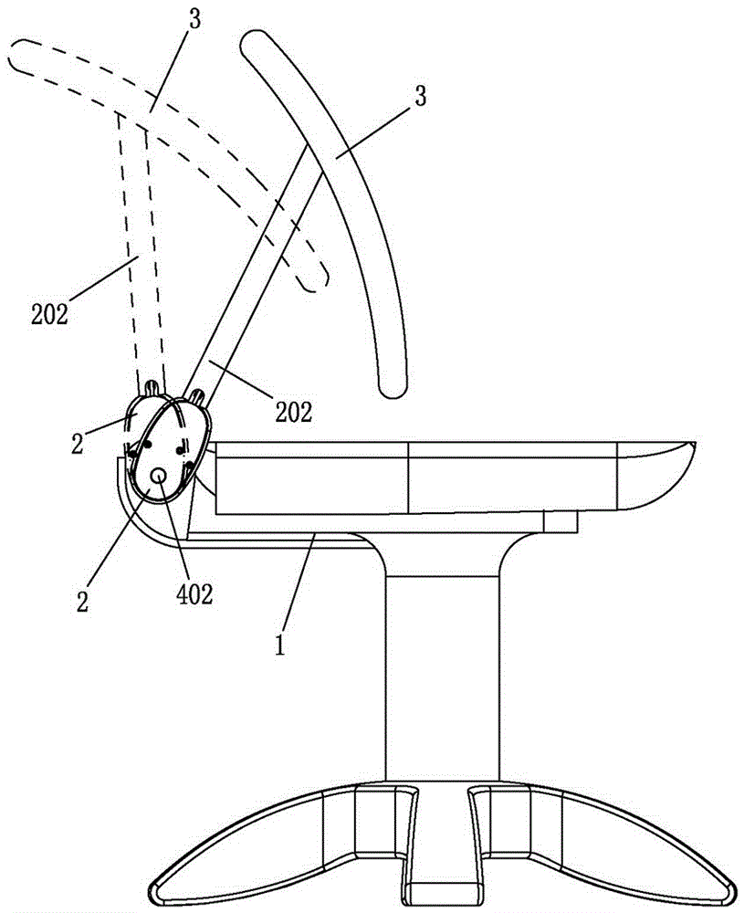
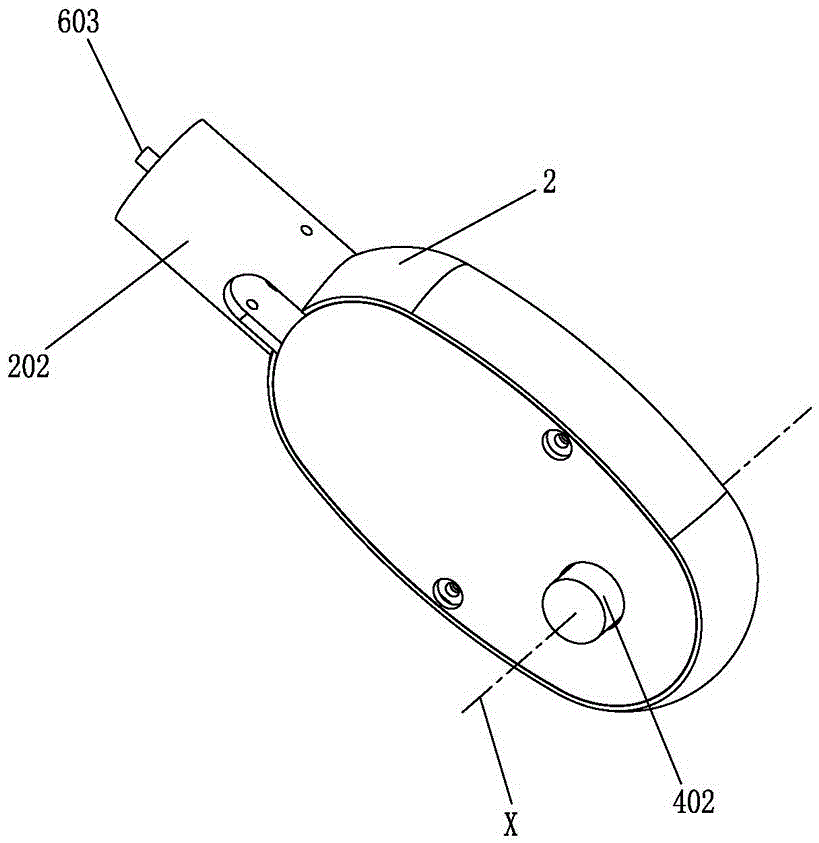
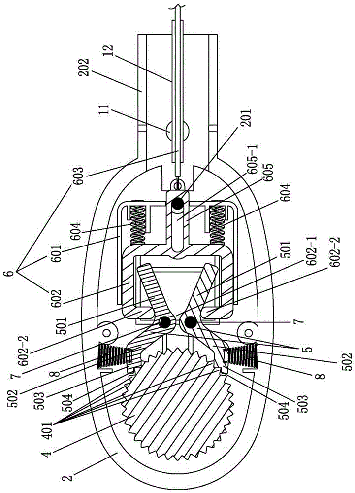
[0042] The first embodiment: as Figure 1 to Figure 3 As shown, a swing mechanism for furniture includes a swing seat 2 installed on the body 1, a support body 3 is connected to the swing seat 2, and the feature is that the swing seat 2 is provided with a fixing part 4 and a ratchet 5. The fixed part 4 (in the form of a gear in this embodiment) is fixedly connected with the main body 1, and the ratchet 5 is driven and moved by the drive assembly 6, so that the ratchet 5 and the fixed part 4 are formed to cooperate or separate, and the swing seat 2 is relatively fixed correspondingly Part 4 realizes positioning or rotation.
[0043] The positioning is equivalent to two-way locking, which means that the swing seat 2 cannot rotate clockwise or counterclockwise relative to the axis X of the fixed part within the normal use range of the product.
[0044] Said rotation is equivalent to two-way rotation, which means that the swing seat 2 can rotate clockwise or counterclockwise rela...
no. 2 example
[0059] The second embodiment: as Figure 4 As shown, this embodiment is similar to the first embodiment, the difference is that:
[0060] A fixing part 4 and a pawl 5 are arranged in the swing seat 2, teeth 401 are arranged on the fixing part 4, a sliding groove 202 suitable for guiding and sliding of the ratchet 5 is provided on the swing seat 2, and one end 501 of the ratchet 5 The sliding groove 202 is extended to connect with the drive assembly 6, and the other end 502 of the ratchet 5 extends out of the sliding groove 202 to form a fit or separation with the teeth 401 on the fixing part 4; change, but its working principle and function are the same as those of the first embodiment; wherein a third return spring 606 (the third The return spring 606 is equivalent to the first return spring of the first embodiment), the drive assembly 6 is a pull rope (wire rope), the drive assembly 6 passes through the spring seat 13 and is connected to the end 501 of the ratchet 5, and th...
no. 3 example
[0061] The third embodiment: as figure 1 and Figure 5 As shown, this embodiment is similar to the first embodiment, the difference is that:
[0062] Two fixing parts 4 and two ratchets 5 are arranged inside the swing seat 2, teeth 401 are arranged on the fixing part 4, and the two fixing parts 4 are engaged with each other, any fixing part 4 is fixedly connected with the body 1, and the two fixing parts 4 are fixedly connected to the body 1. One end 501 of the ratchet 5 is connected to the driving assembly 6 (same as the first embodiment), and the other end 502 of the ratchet 5 is matched with or separated from the teeth 401 on the two fixing parts 4. This embodiment also adopts the two parts in the first embodiment. The first back-moving spring 604 resets the guide frame 602. Except that two mutually engaging fixing parts 4 are provided, the other structures are the same as in the first embodiment; Changes, but its working principle and effect are the same as the above sch...
PUM
 Abstract
Description
Claims
Application Information
 - R&D
- Intellectual Property
- Life Sciences
- Materials
- Tech Scout
- Unparalleled Data Quality
- Higher Quality Content
- 60% Fewer Hallucinations
Browse by: Latest US Patents, China's latest patents, Technical Efficacy Thesaurus, Application Domain, Technology Topic, Popular Technical Reports.
© 2025 PatSnap. All rights reserved.Legal|Privacy policy|Modern Slavery Act Transparency Statement|Sitemap|About US| Contact US: help@patsnap.com


