
Piezoelectric ceramic actuator linear displacement driving circuit and implementation method thereof

A piezoelectric ceramic and linear displacement technology, which is applied in battery circuit devices, current collectors, electric vehicles, etc., can solve the problems of high cost, large voltage drop loss, and low reliability, and achieve simple structure, low cost, and high reliability. high effect

Inactive Publication Date: 2021-10-08
一念传感科技深圳有限公司
View PDF7 Cites 0 Cited by
  • Summary
  • Abstract
  • Description
  • Claims
  • Application Information

AI Technical Summary

Problems solved by technology

[0004] When the high-voltage operational amplifier amplifies the signal amplitude, it works in the linear adjustment area. When the output drives the piezoelectric ceramic actuator, the internal voltage drop loss is large, which may easily cause the amplifier chip to overheat and damage the device. In addition, the high-voltage operational amplifier needs a symmetrical positive circuit for normal operation. , Negative dual power supply, the circuit to realize positive and negative high-voltage power output is complex, the number of components is large, the volume is large, the cost is high and the reliability is low

Method used


Image

  • Piezoelectric ceramic actuator linear displacement driving circuit and implementation method thereof
  • Piezoelectric ceramic actuator linear displacement driving circuit and implementation method thereof
  • Piezoelectric ceramic actuator linear displacement driving circuit and implementation method thereof

Examples


Embodiment 1

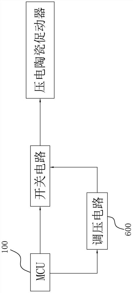
[0075] refer to image 3 and Figure 4 , the embodiment of the present application provides a piezoelectric ceramic actuator linear displacement driving circuit, mainly including MCU100, a voltage regulating circuit 600, a switch circuit and a piezoelectric ceramic actuator, wherein the piezoelectric ceramic actuator can be equivalent to a piezoelectric ceramic actuator Electroceramic equivalent circuit 400. see Figure 5 .

[0076] The first signal output end of the MCU100 is used to output a square wave drive signal with a determined duty ratio; the second signal output end is used to output a DC voltage regulation signal; the input end of the voltage regulation circuit 600 is connected to the second signal output end of the MCU100 for The received DC voltage regulation signal is amplified to form an initial voltage and supply power to the piezoelectric ceramic equivalent circuit 400 . The voltage regulation circuit 600 can use an existing DC amplifier circuit. In an emb...

Embodiment 2

[0087] see Figure 8 , the application provides a piezoelectric ceramic actuator linear displacement drive implementation method, including:

[0088] S100, acquiring an initial voltage and a square wave driving signal;

[0089] The initial voltage is output by the voltage regulating circuit 600, and the square wave drive signal is output by the MCU100; the initial voltage can be adjusted based on the programming of the MCU100 to adapt to the output of different linear displacements of piezoelectric ceramics; the square wave control signal is passed through high and low level switching and duty cycle, control switching circuits.

[0090] S200, driving a pair of switches to act alternately based on the square wave driving signal, so as to control the piezoelectric ceramic equivalent circuit 400 formed by the piezoelectric ceramic actuator to charge and discharge based on the initial voltage;

[0091] The switch circuit is composed of a pair of switches, and the square wave dri...


PUM


Abstract

The invention discloses a piezoelectric ceramic actuator linear displacement driving circuit and an implementation method thereof. The method comprises the following steps: acquiring an initial voltage and a square wave driving signal; driving a pair of switches to act alternately based on the square wave driving signal so as to control a piezoelectric ceramic equivalent circuit formed by a piezoelectric ceramic actuator to charge and discharge by taking an initial voltage as a reference; wherein the terminal voltage of the piezoelectric ceramic equivalent circuit is linearly changed along with the charging and discharging time in the charging and discharging processes, and the charging and discharging of the piezoelectric ceramic equivalent circuit are alternately carried out to realize the linear displacement driving of the piezoelectric ceramic actuator. Compared with the prior art, the scheme has the advantages that a high-voltage operational amplifier is omitted, the number and the size of circuit devices are reduced, the cost is greatly reduced, and the reliability of operation and equipment is improved.

Description

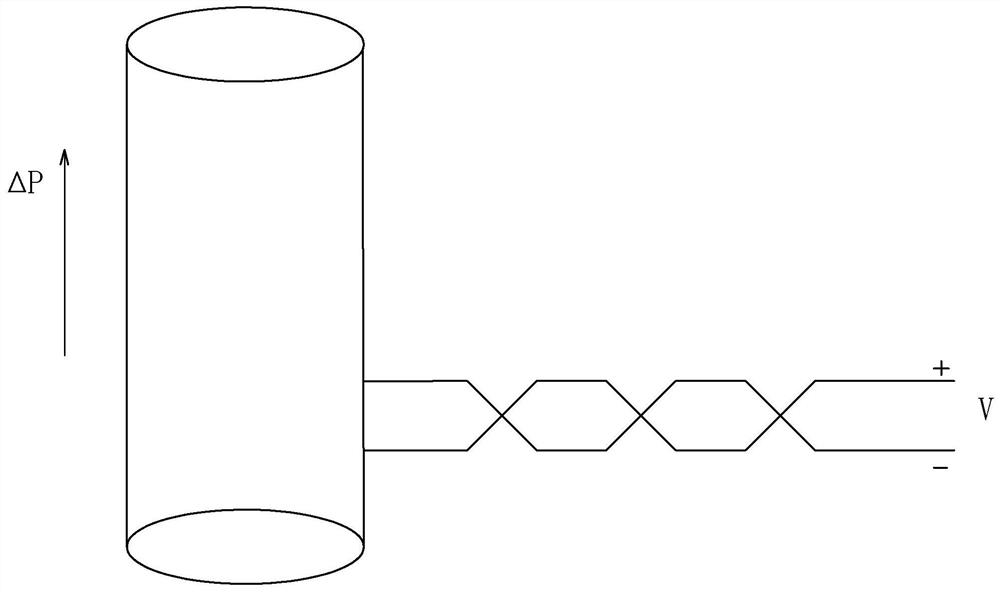
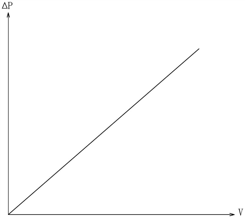
technical field [0001] The present application relates to the field of precision micro-displacement technology applied to optical instruments, in particular to a piezoelectric ceramic actuator linear displacement drive circuit and its implementation method. Background technique [0002] Piezoelectric ceramic actuators are often used in the fields of optics and lasers to achieve high-resolution precise linear micro-displacement of connected parts. The interior of the piezoelectric ceramic actuator is a circular tubular voltage-driven deformation device composed of several piezoelectric ceramic sheets stacked in series or in parallel. DC voltage is applied to the positive and negative ends of the piezoelectric ceramic actuator. Several ceramic sheets stacked inside A tiny deformation displacement and output torque are produced, and the displacement is proportional to the voltage applied across the ceramic. like figure 1 , figure 2 As shown, the greater the voltage V applie...

Claims


Application Information

Patent Timeline
IPC IPC(8): H02J7/00H02M3/156H02N2/02H02N2/06
CPCH02J7/0068H02J7/007H02M3/156H02N2/001H02N2/02H02N2/06
Inventor 苏泊榕钟建胜王俊杨王曜
Owner 一念传感科技深圳有限公司
Learn More