Punch for mechanical connection, mechanical connection device and mechnical connection member

A technology of mechanical connection and punch, which is applied in the field of mechanical connection punch, mechanical connection device and mechanical connection components, which can solve the problems of space limitation of plastic flow, inability to interlock S1 to become larger, and inability to obtain sufficient joint force, etc. Achieve good bonding and improve bonding strength

Inactive Publication Date: 2016-06-22
SUZUKI MOTOR CORP
View PDF12 Cites 4 Cited by
  • Summary
  • Abstract
  • Description
  • Claims
  • Application Information

AI Technical Summary

Problems solved by technology

[0004] However, Figure 11 In the mechanical connection device in the prior art shown, because of its simple cylindrical concave die 104, the space where the upper and lower plates 102, 103 can plastically flow in the outer diameter direction when they are joined is limited.
Therefore, even with the lower plate 103 in the Figure 11 The material in the part surrounded by the circle indicated by the arrow A flows, and cannot retreat to any place, which becomes a large resistance to the above-mentioned plastic flow
Therefore, in the above-mentioned conventional mechanical connection device, the interlock S1 of the upper and lower plates 102, 103 cannot be increased due to the resistance to plastic flow, and as a result, sufficient joining force cannot be obtained.

Method used


Image

  • Punch for mechanical connection, mechanical connection device and mechnical connection member
  • Punch for mechanical connection, mechanical connection device and mechnical connection member
  • Punch for mechanical connection, mechanical connection device and mechnical connection member

Examples


Embodiment Construction

[0045] Below, refer to Figure 1 to Figure 7 , an embodiment of the punch for mechanical connection, the mechanical connection device, and the mechanical connection member of the present invention will be described in detail.

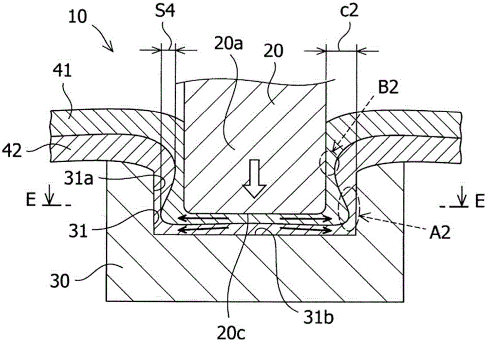
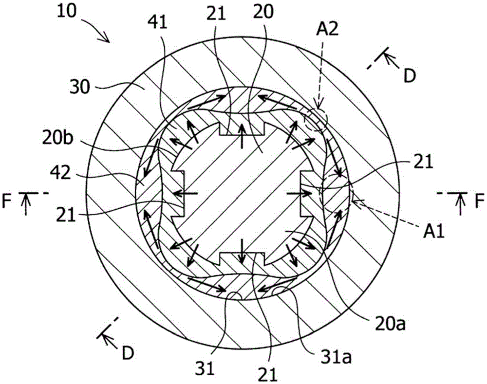
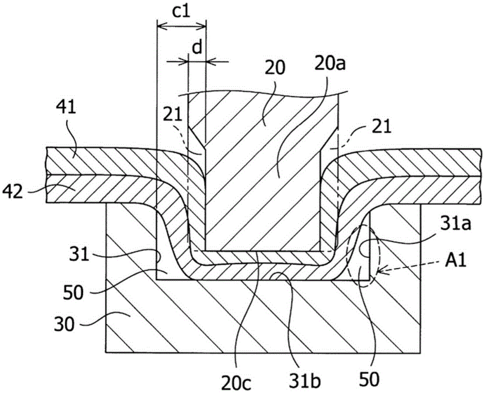
[0046] The mechanical connection device 10 of the present embodiment has such figure 1 A punch (hereinafter, referred to as a punch) 20 for mechanical connection is shown. Such as figure 2 As shown, the cross-sectional shape of the punch 20 is substantially circular, and the punch 20 has four grooves 21 axially extending from the side of the tip 20c on the peripheral side 20b of the tip 20a. The cross section of the groove portion 21 has a quadrangular shape, and the groove portion 21 is formed at equal intervals in the circumferential direction. Thus, the gap between the deep portion of the groove portion 21 at the portion of the tip portion 20a of the punch 20 having the groove portion 21 and the vertical wall surface 31a on the side of the conca...


PUM

PropertyMeasurementUnit
diameteraaaaaaaaaa
depthaaaaaaaaaa
lengthaaaaaaaaaa

Abstract

The invention provides a punch for mechanical connection, a mechnical connection device and a mechnical connection member so that full boding strength can be obtained even when board thickness and strength deviation of boards occurs. In the punch for mechanical connection,a groove (21) or a protruding strip extending along an axial dirction of the top end of the punch (20) is formed on the circumferential lateral surface (20b) of the top end portion (20a) of the punch (20).

Description

technical field [0001] The present invention relates to a punch for mechanical connection (Japanese: メカカニカルクリンチ), a mechanical connection device, and a mechanical connection member. Completed mechanical connection components. Background technique [0002] It has been known for a long time that, for a plurality of stacked metal plates, the metal plates are plastically deformed by punches and dies, and these metal plates are riveted together, that is, the so-called mechanical connection joint (refer to Figure 11 ). In this mechanical connection joining, the punch 101 is lowered, for example, two metal plates (hereinafter referred to as upper and lower plates) 102, 103 are pressed into the concave portion 104a of the die 104, and then, as the final stage of joining, in order to align the punch 101 applies a greater force to pressurize, that is, to perform the so-called setting press (Japanese: 决め抱し), and the upper and lower plates 102, 102, 103 is crushed in the plate thickn...

Claims


Application Information

Patent Timeline
Patent Type & Authority Applications(China)
IPC IPC(8): B21D37/10B21D39/02
CPCB21D37/00B21D39/031B21D37/10B21D39/026
Inventor 山内亮
Owner SUZUKI MOTOR CORP
Why Eureka
Try Eureka