

Methods and apparatus for a stent having an expandable web structure and delivery system
- Summary
- Abstract
- Description
- Claims
- Application Information
AI Technical Summary
Benefits of technology
Problems solved by technology
Method used
Image

Examples
Embodiment Construction
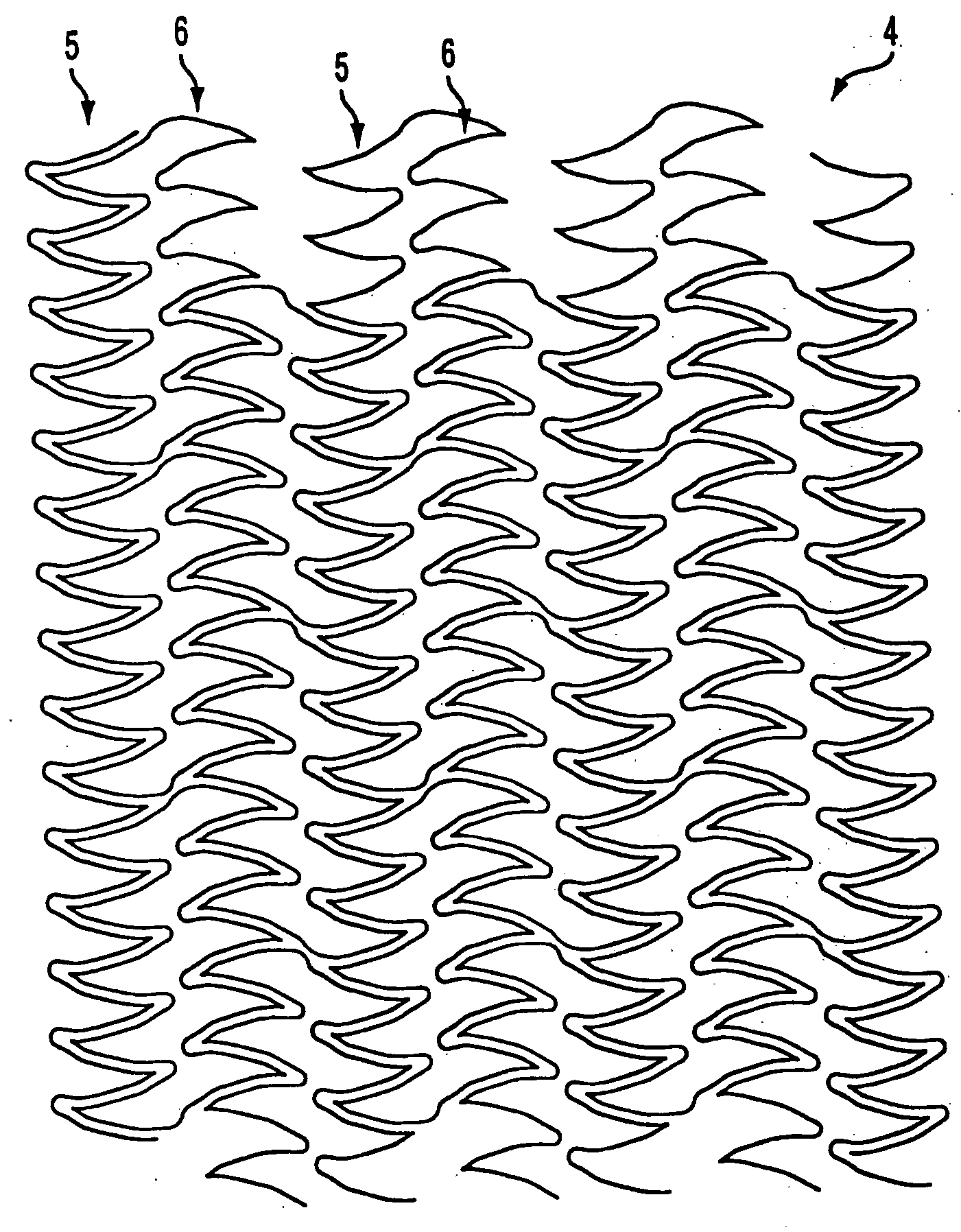
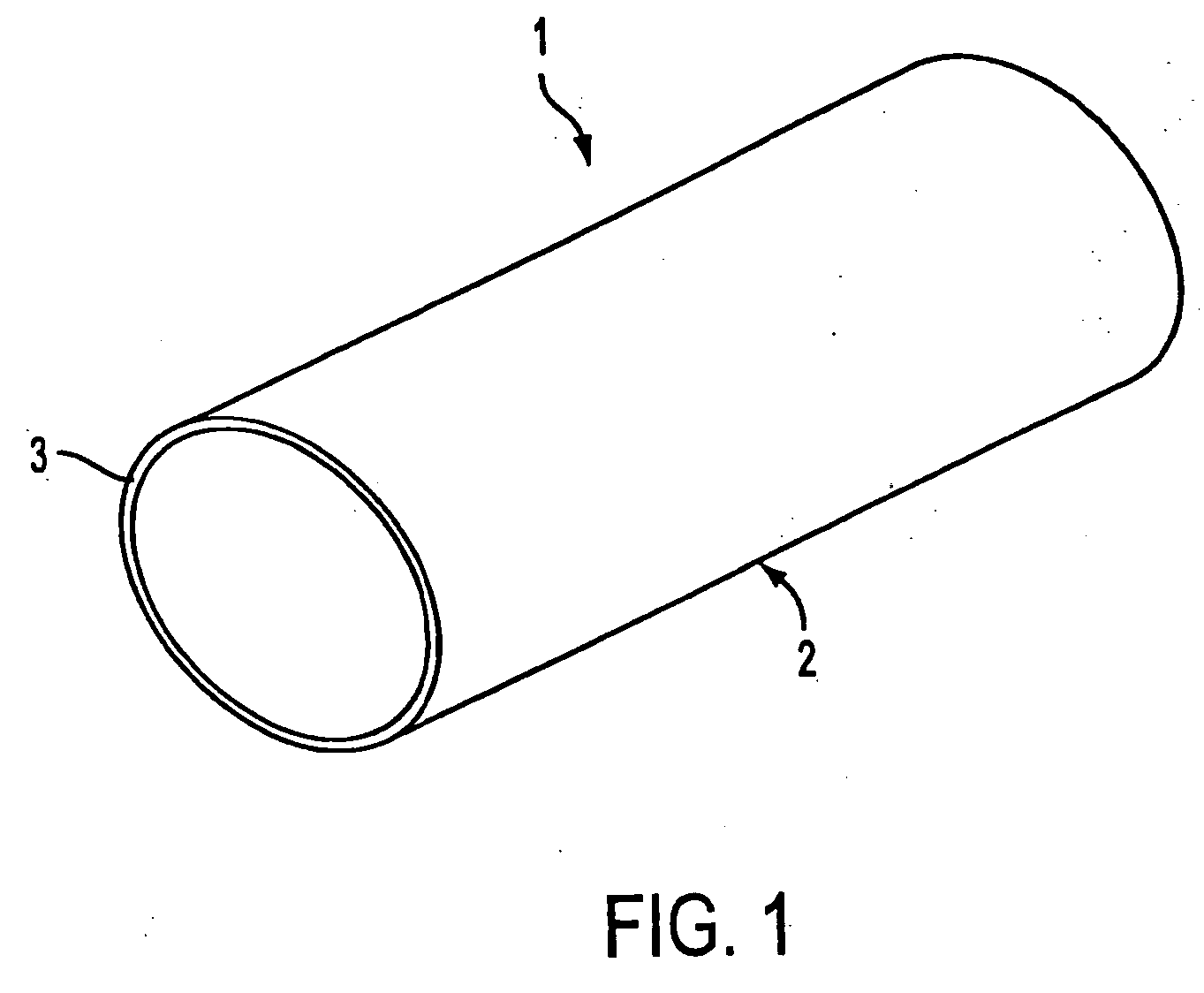
[0030] Referring to FIG. 1, stent 1 comprises tubular flexible body 2. Tubular flexible body 2, in turn, comprises wall 3 having a web structure, as described hereinbelow with respect to FIGS. 2-9. Stent 1 and its web structure are expandable from a contracted delivery configuration to an expanded deployed configuration. Depending on the material of fabrication, stent 1 may be either self-expanding or expandable using a balloon catheter. If self-expanding, the web structure is preferably fabricated from a superelastic material, such as a nickel-titanium alloy. Furthermore, stent 1 preferably is fabricated from biocompatible or biodegradable materials. It also may be radiopaque to facilitate delivery, and it may comprise an external coating C that retards thrombus formation or restenosis within a vessel. The coating alternatively may deliver therapeutic agents into the patient's blood stream.
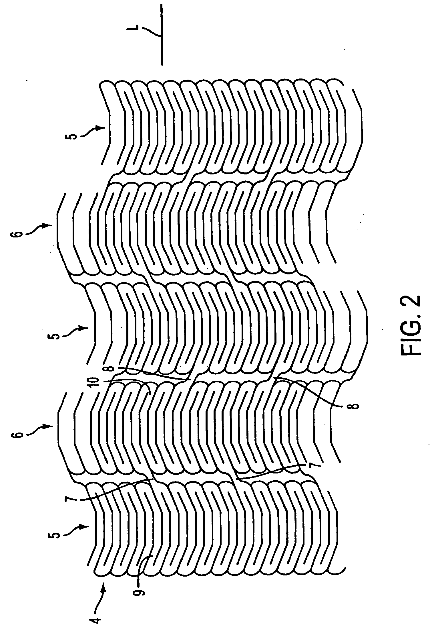
[0031] With reference to FIGS. 2-4, a first embodiment of the web structure of stent 1 is de...
PUM
 Abstract
Description
Claims
Application Information