

Methods and apparatus for stenting comprising enhanced embolic protection coupled with improved protections against restenosis and thrombus formation
- Summary
- Abstract
- Description
- Claims
- Application Information
AI Technical Summary
Benefits of technology
Problems solved by technology
Method used
Image

Examples
Embodiment Construction
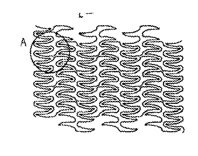
[0084]The present invention relates to stent grafts having an expandable web structure, the stent grafts configured to provide enhanced embolic protection and improved protection against restenosis and thrombus formation. These attributes are attained by attaching to a stent a biocompatible material that is impermeable to emboli but permeable to ingrowth of endothelial cells. Attaching the material to the stent also distributes forces applied to or by the apparatus, and facilitates recrossing into the lumen of the apparatus post-implantation with guide wires, balloons, etc. Thus, unlike previously known bare stents, the present invention provides improved protection against embolic release, a smoother surface for recrossing, and better distribution of forces applied to or by the apparatus. Moreover, unlike previously known, non-porous stent grafts, the present invention provides enhanced protection against thrombus formation and restenosis via rapid endothelialization.
[0085]Prior to...
PUM
| Property | Measurement | Unit |
|---|---|---|
| Angle | aaaaa | aaaaa |
| Length | aaaaa | aaaaa |
| Length | aaaaa | aaaaa |
Abstract
Description
Claims
Application Information