Balloon catheter having a shaft with a variable stiffness inner tubular member

a catheter shaft and variable stiffness technology, applied in the field of catheters, can solve the problems of low bending stiffness of the catheter shaft and inhibit the positioning of the balloon across the stenosis, and achieve the effects of reducing the wall thickness, increasing the wall thickness, and reducing the axial compression stiffness

Inactive Publication Date: 2008-02-21
ABBOTT CARDIOVASCULAR
View PDF10 Cites 34 Cited by
  • Summary
  • Abstract
  • Description
  • Claims
  • Application Information

AI Technical Summary

Benefits of technology

[0005] The invention is directed to a balloon catheter having an elongated shaft and a balloon on a distal shaft section, the elongated shaft comprising an outer tubular member, and an inner tubular member with a bonded portion along which an outer surface of the inner tubular member is bonded to an inner surface of the outer tubular member. The inner tubular member has a distal portion distal to the bonded portion with higher axial compression stiffness and column strength than a proximal portion of the inner tubular member. The catheter has improved trackability, axial collapse resistance, pushability, and crossability, for improved ability to position the balloon at a desired location in a patient's body lumen.
[0007] The bonded portion of the inner tubular member links the inner tubular member to the outer tubular member, preferably at or adjacent to a stiffness transition in the inner tubular member. Specifically, a distal portion of the inner tubular member located distal to the bonded portion has a higher axial compression stiffness and column strength than a proximal portion of the inner tubular member located proximal to the bonded portion. Additionally, in one embodiment, the proximal portion of the inner tubular member has a lower bending stiffness than the distal portion of the inner tubular member. Preferably, the bonded portion is located at (i.e., radially aligned with) or longitudinally adjacent to the proximal end of the balloon. In a presently preferred embodiment, the bonded portion has a distal end located proximal to the balloon and typically a relatively short distance from the proximal end of the balloon and a relatively long distance from the proximal end of the inner tubular member. As a result, the length of the distal portion of the inner tubular member extending distally from the bonded portion, through the balloon interior to the distal end of the inner tubular member, is minimized relative to the length of the proximal portion of the inner tubular member. The configuration provides a maximum length to the highly flexible proximal portion of the inner tubular member. In one embodiment, the distal portion of the inner tubular member has a length equal to about 1 to about 5% of the length of the entire shaft. By linking a portion of the inner tubular member to the outer tubular member near the proximal end of the balloon, the axial compression stiffness of the proximal portion of the inner tubular member has little or no influence on the amount of axial load that is carried by the balloon. Consequently, in the catheter of the invention, the inner tubular member proximal portion has a low bending stiffness and a concurrently low axial stiffness, with the outer tubular member carrying a substantial portion of the total axial force along the shaft up to the adjoining balloon. Distal to the outer tubular member, the distal portion of the inner tubular member is provided with sufficient column stiffness and strength to prevent or inhibit it from elastically shortening or telescopically collapsing under axial load. As a result, the catheter shaft is highly flexible, and nonetheless transfers the majority of applied axial load to the distal end of the balloon and thereby prevents or inhibits buckling of the balloon during advancement of the catheter in the patient's body lumen.
[0011] In a presently preferred embodiment, the inner tubular member comprises a polymeric tube with a coiled reinforcing member embedded therein. Although the distal portion of the inner tubular member typically has a higher axial compression stiffness and column strength than the proximal portion thereof, the coiled reinforcing member allows the inner tubular member to have a relatively low bending stiffness and high radial collapse resistance throughout, for excellent catheter trackability and guidewire movement even after inflation of the balloon at relatively high inflation pressures. The coiled reinforcing member preferably extends at least in part within the proximal and distal portions of the inner tubular member, and in one embodiment, the coiled reinforcing member extends along the entire length of the inner tubular member. In one embodiment, the coiled reinforcing member has a uniform pitch, stiffness, and / or column strength throughout its length. Alternatively, the coiled reinforcing member extending along the distal portion of the inner tubular member has a tighter coil pitch (i.e., more closely spaced coils) than along the proximal portion of the inner tubular member, or otherwise provided with a higher axial stiffness and column strength along the distal portion, to produce the stiffer distal portion of the inner tubular member. For example, a longitudinally extending wire member bonded to the distal portion of the coiled reinforcing member selectively stiffens the distal portion of the inner tubular member. In one embodiment, two types or plies of wire or ribbon form the reinforcing member, with the first type reinforcing the entire length of the inner tubular member and the second type located in the distal portion of the inner tubular member to selectively stiffen the distal portion of the inner tubular member by, for example, preventing the distal coils from moving closer together or bunching under axial load. Similarly, a braided reinforcing member having a variable pick count (number of braid crossover points per unit of axial length) imparting a stiffness transition may alternatively be used to form the inner tubular member. The resulting catheter shaft, formed by the inner and outer tubular members, has an improved low bending stiffness throughout the length of the inner member, for improved trackability.
[0013] The inner tubular member having a stiffness transition can be formed using a variety of suitable methods. For example, in one embodiment, forming the inner tubular member comprises necking a proximal part of a polymeric tube to reduce a wall thickness and an outer diameter thereof without reducing an inner diameter thereof, to thereby reduce the axial compression stiffness of the proximal part of the polymeric tube, and embedding a coiled reinforcing member in the polymeric tube. In another embodiment, forming the inner tubular member comprises increasing the wall thickness of a distal section of a polymeric tubular member having a coiled reinforcing member embedded therein, by a method selected from the group consisting of heat shrinking an outer polymeric layer onto the distal section of the coil reinforced polymeric tubular member, melt bonding an outer polymeric layer onto the distal section of the coil reinforced polymeric tubular member, or dip coating the distal section of the coiled reinforced polymeric tubular member. In another embodiment, forming the inner tubular member comprises joining the distal end of a first tube to a proximal end of a second tube to form a polymeric tubular member, and fusing the polymeric tubular member to a coiled reinforcing member, and the second tube is formed of a polymeric material having a higher Shore durometer hardness or has a wall thickness greater than a wall thickness of the first tube. In another embodiment, forming the inner tubular member comprises fusing a polymeric tube to a braided reinforcing member, the braided reinforcing member having a distal part with a pick count which is higher than a pick count of a proximal part of the braided reinforcing member. In another embodiment, forming the inner tubular member comprises applying an adhesive or melt bondable polymer to a portion of a mandrel, and applying a coil on the mandrel with a distal part of the coil on the adhesive or melt bondable polymer, and fusing a polymeric layer on the coil, to form the coil reinforced polymeric tubular member. In another embodiment, forming the inner tubular member comprises joining the distal end of a coil reinforced polymeric tubular member to the proximal end of a polymer tube having a greater axial stiffness and column strength than the coil reinforced polymeric tubular member. In another embodiment, forming the inner tubular member comprises irradiating or heat stabilizing a distal part of a polymeric tube to increase the stiffness of the distal part of the polymeric tube.
[0014] The balloon catheter of the invention has improved pushability and trackability, due to the low bending stiffness inner tubular member having a bonded portion bonded to the outer tubular member and excellent force transmission through the balloon interior to the distal tip. The shaft configuration prevents or inhibits the balloon from buckling or bunching during advancement in the patient's blood vessel, despite the low bending stiffness of the inner tubular member and resulting excellent trackability. Thus, the catheter shaft of the invention accommodates typically competing considerations in the design of catheters, to facilitate positioning the balloon at a desired location in the patient's blood vessel. These and other advantages of the invention will become more apparent from the following detailed description of the invention and the accompanying exemplary drawings.

Problems solved by technology

However, one difficulty has been providing a catheter shaft having low bending stiffness for optimum trackability, while having sufficiently high axial stiffness (compression modulus) and column strength (collapse point) for maximum transmission of force to the catheter distal end.
A shaft inner tubular member (extending through the balloon interior) having inadequate column stiffness may telescopically collapse under axial load causing balloon bunching / buckling during advancement of the catheter, which consequently inhibits positioning the balloon across a stenosis.

Method used


Image

  • Balloon catheter having a shaft with a variable stiffness inner tubular member
  • Balloon catheter having a shaft with a variable stiffness inner tubular member
  • Balloon catheter having a shaft with a variable stiffness inner tubular member

Examples


Embodiment Construction

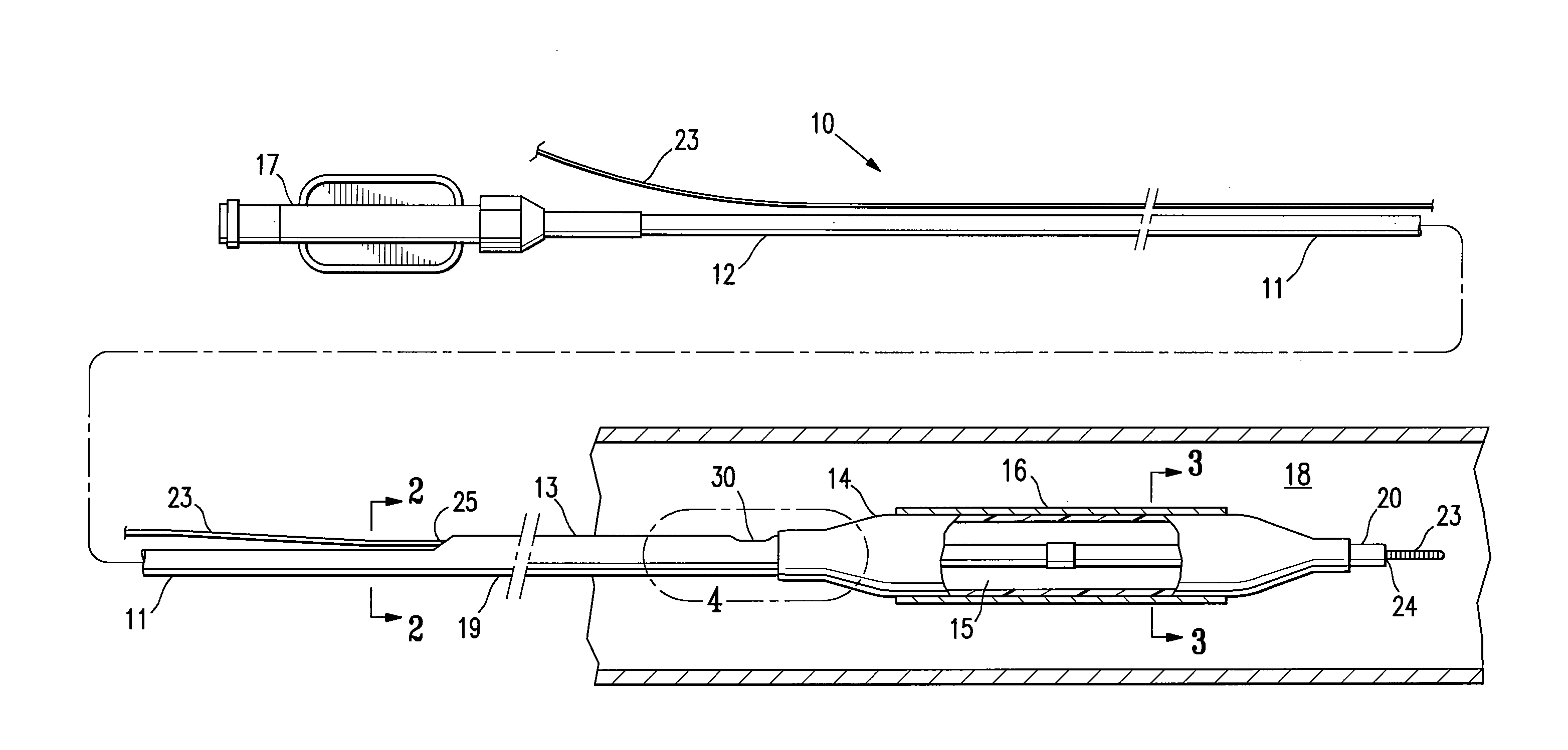
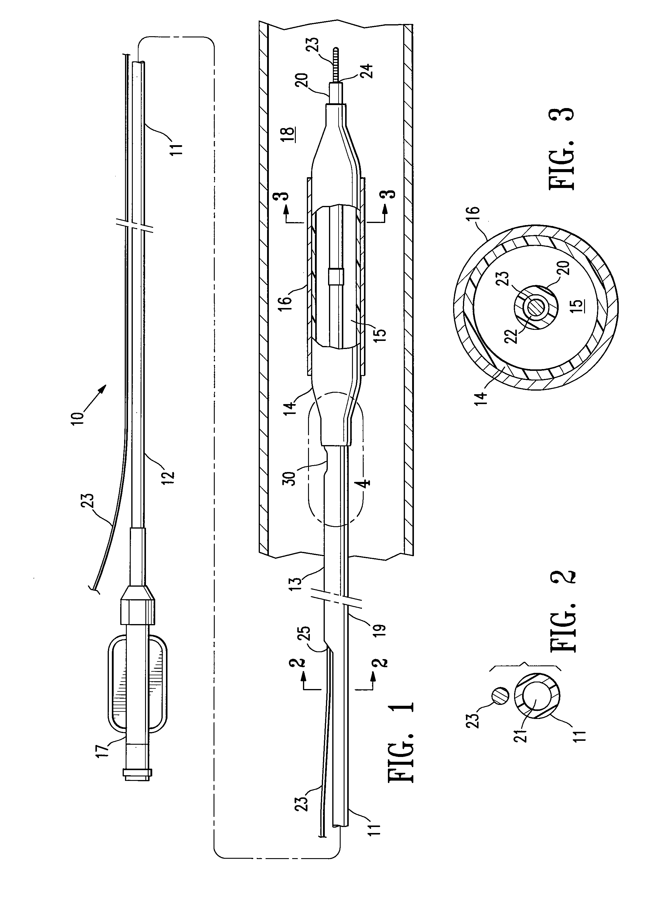
[0020]FIG. 1 illustrates rapid exchange type balloon catheter 10 embodying features of the invention. Catheter 10 generally comprises an elongated catheter shaft 11 having a proximal end, a distal end, a proximal shaft section 12 and a distal shaft section 13 at the distal end of the proximal shaft section, and an inflatable balloon 14 on the distal shaft section. The shaft 11 has an inflation lumen 21, and a guidewire receiving lumen 22. The proximal shaft section 12 comprises a proximal tubular member defining a proximal portion of the inflation lumen 21. The distal shaft section 13 comprises an outer tubular member 19 defining a distal portion of the inflation lumen 21, and an inner tubular member 20 defining the guidewire lumen 22 in fluid communication with a guidewire distal port 24 at the distal end of the catheter and a guidewire proximal port 25 at the proximal end of the inner tubular member 20, configured to slidably receive guidewire 23 therein. Balloon 14 has a proximal...


PUM

PropertyMeasurementUnit
lengthaaaaaaaaaa
lengthaaaaaaaaaa
lengthaaaaaaaaaa

Abstract

A catheter having an elongated shaft and a balloon on a distal shaft section, the elongated shaft comprising an outer tubular member, and an inner tubular member which has a bonded portion along which an outer surface of the inner tubular member is bonded to an inner surface of the outer tubular member. The inner tubular member has a proximal portion proximal to the bonded portion, and a distal portion distal to the bonded portion with higher axial compression stiffness and column strength than the proximal portion thereof. The catheter has improved trackability, axial collapse resistance, pushability, and crossability, for improved ability to position the balloon at a desired location in a patient's body lumen.

Description

BACKGROUND OF THE INVENTION [0001] This invention generally relates to catheters, and particularly intravascular catheters for use in percutaneous transluminal coronary angioplasty (PTCA) or for the delivery of stents. [0002] In percutaneous transluminal coronary angioplasty (PTCA) procedures a guiding catheter is advanced in the patient's vasculature until the distal tip of the guiding catheter is seated in the ostium of a desired coronary artery. A guidewire is first advanced out of the distal end of the guiding catheter into the patient's coronary artery until the distal end of the guidewire crosses a lesion to be dilated. A dilatation catheter, having an inflatable balloon on the distal portion thereof, is advanced into the patient's coronary anatomy over the previously introduced guidewire until the balloon of the dilatation catheter is properly positioned across the lesion. Once properly positioned, the dilatation balloon is inflated with inflation fluid one or more times to a...

Claims


Application Information

Patent Timeline
Patent Type & Authority Applications(United States)
IPC IPC(8): A61M25/10A61F2/958A61M25/00
CPCA61M25/0009A61M25/0054B29C66/5221B29C65/02Y10T156/1002A61M25/10A61M25/005
Inventor SIMPSON, JOHN A.DELGADO, JESSIEWILSON, BRUCEBARBOD, LENNYTORRES, RAMONBROWN, DEVONRITCHIE, QUANCHIN, WILLIAM S.
Owner ABBOTT CARDIOVASCULAR
Why Eureka
Try Eureka